Hello! Welcome to our next lesson in the Design for Manufacturing and Assembly module.
In the previous lesson, we focused on Design for Manufacturability (DFM) for CNC machining. You learned how to modify a part's geometry in Onshape by adding features like fillets and chamfers to accommodate the physical constraints of cutting tools, transforming a difficult design into one that's practical and cost-effective to produce.
Today, we will broaden your DFM expertise by exploring two other ubiquitous manufacturing processes: sheet metal fabrication and casting. Just like CNC milling, these processes have their own unique sets of rules and constraints. As a design engineer, understanding these principles is essential for creating robust, economical parts and for building the kind of real-world portfolio you're aiming for.
Our goal for this lesson is to apply DFM principles for sheet metal and cast parts to a design. We'll cover the fundamental concepts for each process and see how they are applied in practice.
1. DFM for Sheet Metal Fabrication
Sheet metal parts are everywhere—from computer cases and automotive brackets to large industrial enclosures. The process typically involves cutting a flat sheet of metal and then bending or forming it into a 3D shape. Successful design hinges on one core idea: the part must be manufacturable from a flat pattern.

Core Principles of Sheet Metal DFM
To get a comprehensive overview of the key processes and design constraints, let's start with a video.
Top Design Tips & Manufacturing Processes for Mechanical Engineers | DFM Guide
The video 'Top Design Tips & Manufacturing Processes for Mechanical Engineers' from the Engineering Gone Wild channel provides an excellent, concise overview of sheet metal forming processes and their associated DFM constraints.
Please watch the segment from 21:42 to 26:12. As you watch, pay close attention to the DFM constraints discussed, such as: Minimum bend radius Spring back Hole placement relative to edges and bends Flange length
The video highlighted several critical DFM rules. Let's formalize them with the help of a detailed written guide.
Sheet Metal Design: Optimize for Manufacture
The article 'Sheet Metal Design: Optimize for Manufacture' by 3ddfm.com is a great professional resource that summarizes the most important DFM considerations.
Please read the sections titled 'Top 5 DFM Considerations' and 'Common Sheet Metal Design Mistakes'. This will reinforce and expand on the concepts from the video.
Based on these resources, here are the most important rules to remember:
- Bend Radius: The inside radius of a bend should typically be at least equal to the material thickness. Tighter radii risk cracking the material. Keeping radii consistent across the part simplifies tooling.
- Hole and Feature Placement: Holes and other cutouts should be placed away from bends to prevent distortion. A good rule of thumb is to keep the edge of the hole at a distance of at least 2-3 times the material thickness from the bend.
- Bend Relief: To prevent tearing at the edge of a bend, small cuts called "reliefs" are often added. Modern CAD software like Onshape can add these automatically.
- Forming Features: Features like ribs, louvers, or embossments can be stamped into the sheet metal to add significant stiffness without adding material or weight. This is a powerful DFM technique to improve structural performance efficiently.
Applying Sheet Metal DFM in Onshape
Now, let's see how these principles are put into practice within the CAD environment. We'll look at a few key operations from a detailed Onshape tutorial.
First, a powerful technique is to design features in the flat and then specify where the bends occur. This gives you precise control over the final geometry.
Sheet Metal Made Easy in Onshape | Step-by-Step Tutorial
The video 'Sheet Metal Made Easy in Onshape' by Onshape demonstrates how to use a sketched line to create a precise bend. This is a crucial skill for manufacturability.
Watch the clip from 25:28 to 28:20. Notice how the designer creates a simple line sketch on the flat face and then uses the 'Bend' tool. The commentary explains why this is often better than creating a flange, as it allows for perfect alignment of features in the flat pattern before bending.
Next, let's look at adding a strengthening feature.
Sheet Metal Made Easy in Onshape | Step-by-Step Tutorial
The same tutorial shows how to use Onshape's 'Form' tool to add a slotted emboss, a feature that increases the stiffness of the part.
Watch the clip from 38:48 to 42:29. This demonstrates how pre-defined forming tools can be applied to a sheet metal part to create complex features that improve performance.
Finally, the entire process culminates in exporting the flat pattern for the manufacturer.
Sheet Metal Made Easy in Onshape | Step-by-Step Tutorial
The last step in the design process is to generate and export the flat pattern that a manufacturer will use.
Watch from 47:00 to 49:18. This section shows how to inspect the final flat pattern and export it as a DXF/DWG file, which is the standard deliverable for laser cutters or water jets.
By designing with the flat pattern in mind and using tools to add bends and forms intelligently, you create a part that is not just conceptually correct, but also manufacturable.
2. DFM for Cast Parts
Casting involves pouring molten material into a mold and letting it solidify. It's ideal for producing complex, high-volume parts. We'll focus on die casting, where metal is injected into a reusable steel mold (a "die") under high pressure.
Just as with sheet metal, casting has a unique set of physical rules that must be respected in the design.
Core Principles of Casting DFM
Let's begin with another clip from our overview video.
Top Design Tips & Manufacturing Processes for Mechanical Engineers | DFM Guide
The 'Top Design Tips' video also has a great segment on casting that introduces the fundamental DFM constraints.
Please watch the segment from 25:57 to 29:18. Focus on the key constraints for casting: Shrinkage Uniform wall thickness Draft angles Filleting sharp corners
To build on this, we'll consult a professional design guide from Chicago White Metal Casting, a leader in the industry. This resource is exactly the kind of document you'd use in a professional engineering role.
The CWM Die Casting Design and Specification Guide
This 'Die Casting Design and Specification Guide' provides detailed, industry-standard guidelines. We'll focus on the core DFM principles.
Please review the following sections in this guide: Page 5, 'Importance of a Casting’s Parting Line': Understand what the parting line is and why its location is a critical design decision. Page 6, 'Minimizing Part Porosity': Note how variations in wall thickness contribute to defects. Page 6, 'Assuring Longer Die Life': Pay attention to the advice on avoiding sharp corners.
Let's synthesize these concepts into actionable DFM rules for casting:
- Draft Angle: This is arguably the most important rule. All surfaces parallel to the direction the mold opens must be slightly angled (tapered). This "draft" allows the part to be ejected from the mold without being damaged or getting stuck. A typical draft angle is 1-3 degrees.
- Uniform Wall Thickness: Drastic changes in wall thickness cause uneven cooling. Thicker sections cool slower, which can lead to shrinkage, warping, and internal voids (porosity). Aim for a consistent thickness throughout the part.
- Fillets and Radii: Sharp internal corners create stress concentrations in the cast part and in the die itself, leading to cracks. Generous fillets should be used on all internal and external corners.
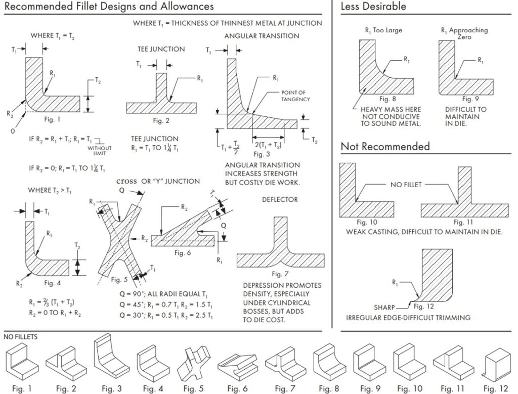
- Parting Line: This is the line where the two halves of the mold meet. Its placement affects where flash (excess material) will form, which surfaces can have the best finish, and the overall complexity and cost of the die. While the final decision rests with the die casting engineer, designing with a simple, flat parting line in mind is good practice.
Test your understanding!
Imagine you are designing the simple L-bracket shown below to be die-cast.
Based on the DFM principles for casting:
- Where would you place the parting line to make the die as simple as possible?
- Which surfaces would require a draft angle?
- Where would you need to add fillets?
Show answer
- Parting Line: The most logical place for the parting line would be along the flat back face of the 'L' shape. This creates a simple two-part mold with no undercuts.
- Draft Angle: All surfaces perpendicular to that back face would need draft. This includes the outer vertical and horizontal faces, the inner vertical and horizontal faces, and the inner wall of the hole.
- Fillets: A generous fillet would be needed at the sharp internal corner where the two legs of the 'L' meet. A smaller fillet should also be added to the sharp external corner for strength and die life. The edges around the hole should also be rounded (chamfered or filleted).
Conclusion
You have now surveyed the fundamental DFM principles for three major manufacturing processes: CNC machining, sheet metal fabrication, and casting. While the specific rules differ, the underlying philosophy is the same: designing with an awareness of the physical process leads to better, cheaper, and more reliable parts.
Key Takeaways:
- Sheet Metal DFM: The primary goal is to create a part that can be unfolded into a flat pattern. Key rules involve using appropriate bend radii (>= thickness), keeping holes away from bends, and using forming features to add stiffness.
- Casting DFM: The design must allow for easy removal from the mold and smooth flow of molten material. The essential rules are to include draft angles on all vertical walls, maintain uniform wall thickness, and use generous fillets on all corners.
Preview of the Next Lesson:
So far, we've focused on designing individual parts. In our next lesson, we'll zoom out to the assembly level. You will learn to apply techniques for part count reduction and component standardization in an assembly, which are key tenets of Design for Manufacturing and Assembly (DFMA).