Hello! Welcome back.
In our last lesson, we explored the "why" behind the rules of CNC machining, focusing on the fundamental constraints like tool geometry, tool access, and tool stiffness. You learned to identify the characteristics of a design that would make it difficult or expensive to manufacture.
Today, we transition from identifying problems to solving them. The learning outcome for this lesson is to modify part geometry in OnShape to improve machinability, such as adding corner radii. We will take the theoretical constraints you've learned and apply them directly to a part's geometry, turning a difficult design into a manufacturable one. This is a core skill in Design for Manufacturing (DFM) and a crucial one for creating a professional engineering portfolio.
1. The Problem: Sharp Internal Corners
As we discussed, the most common and fundamental constraint in 3-axis CNC milling comes from tool geometry. A spinning, cylindrical cutting tool simply cannot create a perfectly sharp internal corner.
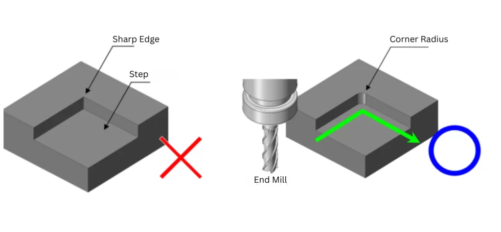
This means that any design with sharp internal corners needs to be modified. Let's look at the primary ways to do this.
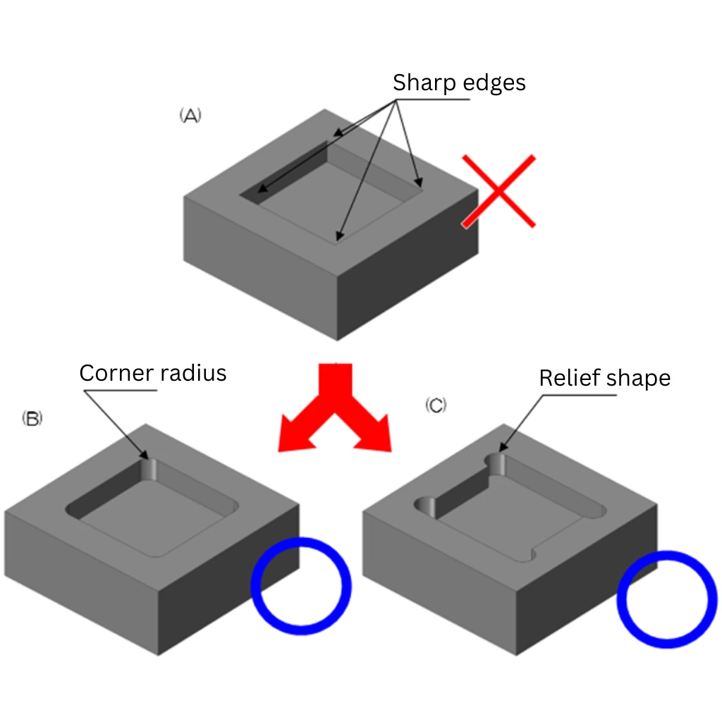
We will now focus on implementing solutions (B) and (C).
2. Solution 1: Designing with Internal Radii (Fillets)
Adding a fillet to an internal corner is the standard approach to make a part machinable. However, simply adding any fillet isn't enough. An effective design follows specific rules to optimize for cost and quality.
To understand these rules, please read the following section from the OnShape blog. It provides excellent visual explanations for designing internal fillets.
The article 'CNC Machining 101' from OnShape explains the key rules for sizing internal fillets for machinability.
Please read the section titled 'Vertical Internal Fillets'. Focus on: The rule of thumb relating fillet radius (R) to wall height (H). The explanation of why the part's fillet radius must be larger than the tool's radius.
Let's summarize the two critical rules from that reading:
- Radius-to-Depth Ratio: A good rule of thumb is to make the fillet radius (R) at least one-third of the adjacent wall height (H).
This ensures that the tool used to create the pocket isn't excessively long and thin (i.e., it has a low Length-to-Diameter ratio), which maintains tool stiffness and prevents chatter and deflection. - Radius vs. Tool Size: Always design the fillet radius to be slightly larger than a standard tool radius. For example, if the machinist will use a 10mm diameter tool (5mm radius), designing your fillet to be 6mm is much better than designing it to be 5.0mm. This prevents the tool from engaging 180 degrees in the corner, which can cause it to break or leave a poor surface finish. The larger the radius, the larger and more rigid the tool that can be used, which almost always results in a faster and cheaper process.
Which Fillet Type to Use in Onshape?
Onshape offers several types of fillets (constant radius, constant width, curvature, etc.). For machined parts, the choice is straightforward.
Tech Tip: How and When to Use Fillets in Onshape
This short Tech Tip from OnShape clarifies which fillet type is appropriate for machined parts.
Read the section 'Which Fillet Type to Use' and pay attention to the paragraph that begins 'Parts that are machined...'.
As the article states, machined parts require fixed-radius fillets. This allows the machinist to use a standard, off-the-shelf end mill or bullnose cutter to create the feature. Curvature-continuous fillets are more appropriate for consumer products made via processes like injection molding. In Onshape, this corresponds to the Constant Radius Fillet with a Circular cross-section.
Test your understanding!
You are designing an aluminum bracket with a pocket that is 30mm deep.
- Based on the rule of thumb, what is a good minimum internal corner radius to design?
- A machinist tells you they have 1/2" (12.7mm) and 1/4" (6.35mm) diameter end mills available. Which tool would be preferable for machining the pocket, and what fillet radius would you specify in your CAD model to accommodate it?
Show answer
- The minimum recommended radius is H/3, so 30mm / 3 = 10mm.
- The 1/2" (12.7mm) diameter end mill would be preferable because it is more rigid. Its radius is 6.35mm. A 10mm radius would work perfectly with this tool. However, to optimize even further, you could design the fillet radius to be slightly larger than the tool radius, for example, 7mm or 8mm. An 11mm or 12mm radius would also be excellent choices. The key is that the designed radius is larger than the tool's radius.
3. Solution 2: Designing Corner Reliefs ("Dog-Bones")
What if your design must accommodate a mating part that has a sharp, 90-degree corner? In this case, a simple fillet won't work. The solution is to create a corner relief, often called a "dog-bone" or "T-bone".
This involves intentionally machining past the corner to create clearance. While it might look unusual, it's a standard and effective DFM technique. You saw this in the "How to Design Parts for CNC Machining" video from the last lesson, and it's shown as option (C) in the corner design image we viewed earlier. The diameter of the circular cut for the relief should be just larger than the diameter of the end mill used for the pocket walls.
4. Handling External Corners and Edges
Modifying external corners and edges follows different rules, as they are generally easier to machine.
Let's return to the 'CNC Machining 101' article to see how to handle external features.
Read the sections 'External Fillets' and 'Chamfering and Deburring'. Note the key difference in philosophy between internal and external features.
Key takeaways for external features:
- External Fillets: These are often considered "free" features. Since the tool is already tracing the outside profile of the part, adding a radius to an outside corner doesn't add significant machining time. It's a great way to deburr the part and remove sharp edges that can be a safety hazard.
- Chamfers vs. Fillets for Edge Breaking: For breaking the sharp edges on the top surfaces of your part, it is almost always better to specify a chamfer rather than a fillet, unless a radius is functionally required. A standard 45-degree chamfer tool is a common, versatile tool for a machinist. Modeling a specific fillet radius on a top edge might require a special "form tool," which adds unnecessary cost. Often, a simple note on the drawing like "BREAK ALL SHARP EDGES 0.5mm x 45°" is sufficient.
5. Case Study: Improving a Poorly Designed Part
Now, let's see the dramatic impact these simple changes can have. The following video shows a part that is poorly designed for CNC milling and then shows the modifications that make it much cheaper and easier to produce.
How to Design Parts for CNC Machining
The video 'How to Design Parts for CNC Machining' by Adam Bender includes an excellent case study comparing a poorly designed part to a well-designed one.
Watch the segment from 09:08 to 10:28. Before you see the 'after' version, pause the video and try to identify the problems with the initial design. Then, watch the solution and note the changes made and the significant cost savings achieved.
The key changes that led to a nearly 40% cost reduction were:
- Removing fillets from top edges (could be replaced by a chamfer callout).
- Removing floor fillets that required special bullnose or ball-end tooling.
- Increasing the internal fillet diameters to allow for a larger, more efficient cutting tool.
These are exactly the kinds of modifications that demonstrate a strong understanding of DFM.
Conclusion
You've now moved from theory to practice. By learning how and when to apply fillets, chamfers, and reliefs, you can transform a design from a concept into a manufacturable reality. This not only reduces cost but also shows a level of engineering maturity that is highly valued in industry.
Key Takeaways:
- Modify sharp internal corners with constant-radius fillets in Onshape.
- Use the R > H/3 rule of thumb for sizing internal fillets.
- If a functional sharp corner is needed, use a "dog-bone" relief.
- External fillets are a low-cost way to deburr parts.
- Prefer chamfers over fillets for breaking top edges unless a radius is functionally critical.
Preview of the Next Lesson:
CNC machining is a cornerstone of manufacturing, but it's not the only process. In the next lesson, we will broaden our DFM knowledge to other common methods by learning how to apply DFM principles for sheet metal and cast parts to a design.