Hello! Welcome to the next phase of your engineering journey.
In the last module, you successfully completed your first portfolio project from concept to final documentation. You designed a linear motion system, validated it with FEA, and created a professional technical summary. That process represents the core of a design engineer's work: creating a functional solution.
Now, we'll add a crucial layer of professional practice: Design for Manufacturing and Assembly (DFMA). A great design isn't just one that works; it's one that can be produced efficiently and affordably. This module will give you the tools to make those kinds of design decisions.
Today's lesson is the first step. Your learning outcome is to identify key constraints of 3-axis CNC machining, including tool access, undercuts, and minimum feature sizes. Understanding the "rules of the game" for a common manufacturing process like CNC machining is fundamental to creating practical and cost-effective mechanical parts.
1. The Fundamentals of 3-Axis CNC Machining
First, let's establish a clear mental model of how a 3-axis CNC mill works. It's a subtractive process where a spinning cutting tool moves along three linear axes (X, Y, and Z) to carve a part out of a solid block of material.
This short video provides an excellent visual introduction to the machine's motion and the basic types of cutting tools (end mills) used.
How to Design Parts for CNC Machining
The video 'How to Design Parts for CNC Machining' by Adam Bender starts with a perfect, concise overview of how a 3-axis mill operates.
Watch from the beginning until 02:35. Focus on: The X, Y, and Z axes of motion. The concept of a spinning cutter removing material. The comparison of an end mill to a cantilever beam—this should resonate with your mechanical engineering background. Notice the dramatic effect of tool length on deflection.
The key takeaway is that every feature on your part must be created by this spinning, cylindrical tool moving along these three axes. This simple fact is the source of all the design constraints we're about to discuss.
2. The Five Core Machining Restrictions
Before we dive into specific design rules like "add a fillet here," it's more effective to understand why those rules exist. Nearly all constraints in 3-axis milling stem from five physical limitations.
The following resource provides a clear, structured explanation of these core restrictions. You can choose to watch the video or read the equivalent text guide.
The 'CNC machining design guide' from Hubs (now Protolabs) clearly outlines the fundamental restrictions of the CNC process. Understanding these will help you think like a machinist.
Please read the section titled 'CNC machining design restrictions'. Focus on the five key points: Tool geometry, Tool access, Workpiece stiffness, Tool stiffness, and Workholding. The illustrations provide excellent visual context for each point.
To summarize, these are the five "Whys" of CNC design:
- Tool Geometry: Cutting tools are cylindrical, so they can't create sharp internal corners.
- Tool Access: The tool must be able to physically reach every surface it needs to cut, approaching from above (along the Z-axis).
- Workpiece Stiffness: The part itself can bend or vibrate under cutting forces, especially if it has thin walls or tall, slender features.
- Tool Stiffness: The cutting tool can also bend, especially when it's long and thin. This affects accuracy and surface finish.
- Workholding: The part must be held securely. Features on multiple faces require re-clamping the part (called "setups"), which adds time, cost, and potential for error.
Keep these five principles in mind as we now explore how they translate into specific, actionable design constraints.
3. Key Design Constraints in Practice
Let's now address the specific constraints from our learning outcome—minimum feature sizes, tool access, and undercuts—by connecting them to the core principles you just learned.
A. Minimum Feature Sizes: Pockets & Internal Corners
When you design a pocket or an internal corner, you are dictating the size and shape of the tool that must be used.
-
Internal Radii: Because tools are round (Tool Geometry), you cannot design a perfectly sharp internal corner. You must add a fillet. A larger radius is always better, as it allows for a larger, more rigid tool to be used, reducing machining time and cost. A good rule of thumb is to make the corner radius slightly larger than the tool radius to prevent the tool from binding in the corner.
-
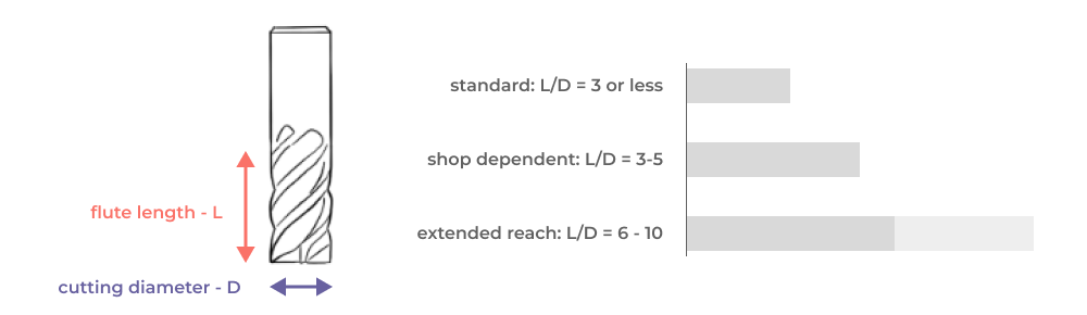
Pocket Depth: The depth of a pocket is limited by Tool Stiffness. To machine a deep pocket, you need a long, skinny tool. As you saw in the first video, this dramatically increases tool deflection, leading to poor accuracy and surface finish. This is often described by the tool's Length-to-Diameter (L/D) ratio.
The following video provides excellent practical advice on sizing internal fillets and the trade-offs involved.
How to Design Parts for CNC Machining
Let's return to Adam Bender's video, which gives a great explanation of how to handle internal fillets and the consequences of violating feature size ratios.
Watch from 02:35 to 03:56. Pay attention to the 'dog bone' corner as a clever solution for when a mating part requires a sharp corner, and the 4:1 height-to-width ratio guideline for tall features.
B. Tool Access and Undercuts
Tool Access is perhaps the most defining constraint of 3-axis machining. If the tool can't reach a feature from the top down, it can't be machined without a more complex setup. This brings us to undercuts.
An undercut is a feature that is 'hidden' or recessed, preventing a standard vertical toolpath from reaching it.

In general, you should avoid undercuts whenever possible in a 3-axis design. They require either special tools (like a "T-slot" or "lollipop" cutter) or rotating the part for an additional setup, both of which significantly increase cost and complexity.
CNC Machining - How to Design Parts for CNC Machining
The Protolabs video 'CNC Machining - How to Design Parts for CNC Machining' has a dedicated section that explains how to design undercuts if they are absolutely necessary.
Watch the segment from 08:07 to 09:12. Focus on the key takeaway: if you must design an undercut, you need to provide sufficient width and clearance for the special tool to access the feature.
Test your understanding!
Imagine you are designing a mounting bracket. Your initial design includes a deep, narrow channel (2mm wide, 20mm deep) and sharp internal corners where the channel meets the main body of the bracket.
Based on the constraints discussed, identify two major machinability issues with this design and explain the core principle behind each issue.
Show answer
-
Issue 1: The deep, narrow channel. The L/D ratio is 10:1 (20mm deep / 2mm wide). This violates the principle of Tool Stiffness. A 2mm diameter end mill long enough to reach the bottom of the channel would be extremely flexible, leading to severe tool deflection, vibration (chatter), poor surface finish, and inaccurate dimensions.
-
Issue 2: The sharp internal corners. This violates the principle of Tool Geometry. A cylindrical cutting tool cannot create a sharp internal corner. This would either be impossible to machine as designed or would require a secondary process like EDM (Electrical Discharge Machining), drastically increasing the cost. The design must be modified to include a radius.
Conclusion
In this lesson, you've learned to see a part through the eyes of a machinist. By understanding the fundamental constraints of 3-axis CNC machining, you can start making design choices that lead to more robust, affordable, and manufacturable parts.
Key Takeaways:
- 3-Axis CNC Machining is a subtractive process where a spinning tool cuts along X, Y, and Z axes.
- Core Constraints are rooted in five principles: Tool Geometry, Tool Access, Workpiece Stiffness, Tool Stiffness, and Workholding.
- Internal Corners must have radii; larger is better. This is due to tool geometry.
- Pocket/Feature Depth is limited by the tool's L/D ratio to maintain tool stiffness and prevent deflection. A ratio of 4:1 or less is a safe guideline.
- Undercuts are features that block standard tool access and should be avoided. If necessary, they require special tooling and careful design for clearance.
Preview of the Next Lesson:
Knowing the constraints is the first half of the battle. The next step is applying that knowledge. In our next lesson, you will learn how to modify part geometry in OnShape to improve machinability. We will take a part with poor design-for-machining features and systematically improve it, turning theory into practice.