Hello! Welcome to your fifth lesson.
In our previous lessons, we individually defined voltage (), the electrical "pressure"; current (), the flow of charge; and resistance (), the opposition to that flow. We established that these are the three fundamental quantities that describe the state of a simple circuit.
Today, we will unite these concepts with one of the most fundamental principles in all of electronics: Ohm's Law. This elegant and simple law describes the relationship between voltage, current, and resistance. Our learning outcome for this lesson is to apply Ohm's law () to calculate voltage, current, and resistance in simple circuits.
We'll start with an intuitive look at this relationship, formalize it mathematically, and then apply it to solve practical problems, including the design of a circuit you will use frequently with your Arduino.
1. An Intuitive Look at Ohm's Law
Before we jump into the equation, it's powerful to have an intuitive feel for how V, I, and R are related. The water analogy we've used before is perfect for this. Imagine voltage is the height difference of a water channel, current is the amount of water flowing, and resistance is an obstacle in the channel.
An intuitive approach for understanding electricity
The video 'An intuitive approach for understanding electricity' by AlphaPhoenix, which we've seen before, has a fantastic demonstration of Ohm's Law using a water trough.
Please watch from 19:37 to 23:26. Observe how the water level (voltage) changes when an impediment (resistor) is placed in the channel. Notice how the water 'piles up' behind the resistor, creating a sudden drop in height (voltage drop).
This visualization captures the essence of Ohm's Law:
- A larger voltage drop (a steeper "hill") across a resistance will cause a larger current (more "flow").
- For a fixed voltage, a larger resistance (a bigger "obstacle") will result in a smaller current.
2. Formalizing Ohm's Law
The German physicist Georg Simon Ohm experimentally discovered that for many materials, the current flowing through them is directly proportional to the voltage applied across them.
This relationship is expressed by the famous equation:
Where:
- is the voltage drop across a component, in Volts (V).
- is the current flowing through the component, in Amperes (A).
- is the resistance of the component, in Ohms ().
This is an empirical law, meaning it is based on experimental observation. Materials that follow this linear relationship, like copper wire and most resistors, are called ohmic. Many components, like diodes and transistors, do not follow this rule and are called non-ohmic.
To help you remember and rearrange the formula, this mnemonic triangle is extremely useful.
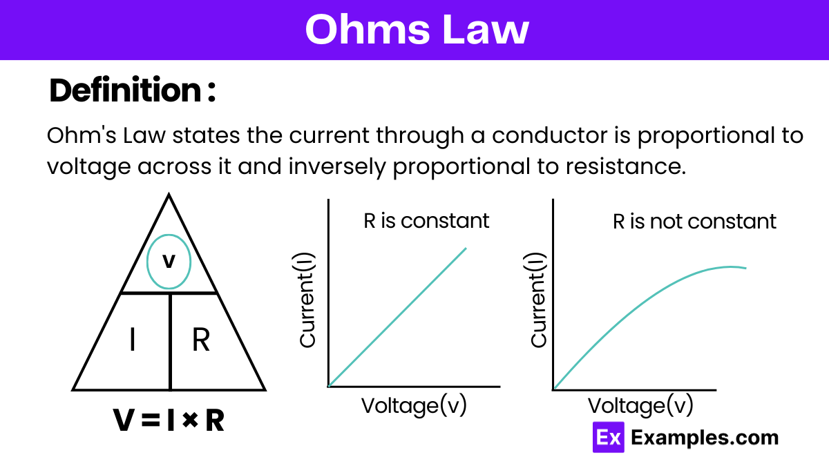
For a more formal definition and context, the following text is a good summary.
Chapter 20. Electric Current, Resistance, and Ohm's Law
The textbook chapter 'Electric Current, Resistance, and Ohm's Law' provides a clear, formal introduction to the law and its implications.
Please read the section '20.2 Ohm’s Law: Resistance and Simple Circuits'. Focus on the definition of Ohm's Law as a cause-and-effect relationship and the definition of an 'ohmic' material.
3. The Physics Behind the Law (A Deeper Dive)
Given your interest in the underlying physics, it's worth seeing how the macroscopic emerges from the microscopic behavior of electrons we discussed in the last lesson. This is not just a random rule; it's a consequence of fundamental principles.
The video 'Understanding Ohm's law' by Sabins provides a concise derivation starting from the atomic level.
Watch the segment from 00:10 to 02:41. Follow the logical steps from electron acceleration and collision (drift speed) to current density, and finally to the familiar V=IR form. This connects the microscopic physics to the macroscopic law.
This derivation beautifully shows how the resistance consolidates all the microscopic properties of the material—its atomic structure, the density of free electrons (), and their collision behavior—into a single, measurable macroscopic value.
4. Applying Ohm's Law: Calculations
Ohm's law is a practical tool for circuit analysis. Let's use it to solve a typical problem.
Example Problem:
Your Arduino kit contains LEDs. A standard red LED operates safely with a current of about 15 mA (0.015 A) and has a "forward voltage drop" of about 2V. If you power your circuit with the Arduino's 5V pin, what value of resistor do you need to place in series with the LED to limit the current?
A simple LED circuit. The resistor R is called a 'current-limiting' resistor.
Solution:
- Identify the voltages. The power source provides 5V. The LED "uses up" 2V of this electrical pressure. This means the remaining voltage must be "dropped" across the resistor.
- Identify the current. We want to limit the current through the entire circuit to 15 mA, or 0.015 A. Since the resistor and LED are in a single loop (in series), the current is the same through both.
- Apply Ohm's Law. Now we can calculate the required resistance using .
So, you would need a 200 resistor. The closest standard value in your kit is likely 220 , which would be a safe choice. We will build this exact circuit in a future lesson!
Test your understanding!
Here are a few problems to practice. You can find more in the OpenStax textbook (LINK) in the "Problems & Exercises" section.
- What current flows through the bulb of a 3.00-V flashlight when its hot resistance is 3.60 ? (Problem 18)
- Calculate the effective resistance of a pocket calculator that has a 1.35-V battery and through which 0.200 mA flows. (Problem 19)
- How many volts are supplied to operate an indicator light on a device that has a resistance of 120 , given that 25.0 mA passes through it? (Problem 21)
Show answers
- Using :
- First, convert current to Amperes: .
Using :
- First, convert current to Amperes: .
Using :
5. A Key Application: The Voltage Divider
One of the most common and useful circuit patterns is the voltage divider. It's a direct and elegant application of Ohm's Law. Its purpose is to take a larger voltage and produce a smaller, proportional output voltage.
This is immediately relevant to your Arduino, which can be damaged by voltages above 5V. If you wanted to measure a 9V battery, how could you do it safely? You would use a voltage divider to scale the 9V down to a voltage within the Arduino's 0-5V range.
Voltage Measurement Using Arduino
The Instructable 'Voltage Measurement Using Arduino' explains the problem and introduces the voltage divider circuit as the solution.
Read 'Step 3: Measuring Voltage Above 5V' and 'Step 4: Building the Voltage Divider'. Focus on the circuit diagram and the formula provided. We are going to derive that formula ourselves.
As the article shows, a voltage divider is simply two resistors ( and ) connected in series to a voltage source (). The output voltage () is taken from the point between them.
The standard voltage divider circuit. will always be less than or equal to .
Let's derive the formula for using Ohm's Law:
- Total Resistance: The two resistors are in a single path (series), so their total resistance is simply their sum.
- Circuit Current: Using Ohm's Law, we can find the total current flowing from the source through both resistors.
- Output Voltage: The output voltage, , is the voltage drop across only the second resistor, . We can apply Ohm's Law again, just to this resistor.
- Combine and Simplify: Now, substitute the expression for from step 2 into step 3.
This gives us the famous voltage divider formula:
This result is powerful. It shows that the output voltage is a fixed fraction of the input voltage, determined solely by the ratio of the resistor values.
Conclusion
This lesson introduced the central equation of DC circuit analysis, Ohm's Law. It is the bedrock upon which much of your future learning will be built.
Key Takeaways:
- Ohm's Law () states that the voltage across an ohmic component is directly proportional to the current flowing through it.
- The law can be rearranged to solve for voltage, current, or resistance.
- It is an essential tool for practical circuit design, such as calculating the correct current-limiting resistor for an LED.
- A key application of Ohm's Law is the voltage divider circuit, which uses two series resistors to produce a smaller output voltage from a larger input voltage, according to the formula .
In our next lesson, we will complete the foundational trio of circuit quantities by exploring electrical power. We'll learn how to calculate the rate at which energy is consumed in a circuit, which manifests as heat or light, using the relationships we've established today.