Introduction
Welcome to your second lesson in the "Memory Hierarchy and Cache Systems" module. In our previous lesson, we established the "why" behind the memory hierarchy—it's the fundamental architectural solution to the massive speed gap between the CPU and main memory. We saw that caches are small, fast memory buffers designed to hold frequently used data close to the processor, creating the illusion of a large, fast memory.
Today, we transition from the "why" to the "how." Our goal is to answer the question: How does a CPU cache actually work? This involves understanding how the cache stores data and, crucially, how it uses a memory address to quickly determine if the requested data is present.
By the end of this lesson, you will be able to describe how CPU caches work, including cache lines, tags, and indexing. We will deconstruct a memory address to see how different parts of it are used to perform this high-speed lookup, starting with the simplest cache design.
The Basic Unit: The Cache Line
First, it's important to understand that when data is moved between main memory and the cache, it's not transferred one byte at a time. Doing so would be inefficient. Instead, data is moved in fixed-size chunks called cache lines (or cache blocks).
This design decision is a direct application of the principle of spatial locality, which we discussed briefly in the context of the memory hierarchy. The idea is that if a program accesses a particular memory location, it's very likely to access nearby memory locations soon. By fetching a whole block of surrounding data (e.g., 64 bytes) at once, the cache speculatively loads data that will probably be needed next, saving a future trip to main memory.
11.4. CPU Caches - Dive Into Systems
To start, let's get a formal definition of a cache line and its role. Please read the first part of section 11.4.1 in the 'Dive into Systems' textbook.
Read the section titled '11.4.1. Direct-Mapped Caches'. Focus on the descriptions of a cache data block and metadata. You can stop just before the 'Locating Cached Data' subsection.
As the text explains, each cache line consists of two main parts:
- Data Block: The actual chunk of data copied from main memory.
- Metadata: Information about the data. The two most important pieces of metadata, which we will explore next, are the valid bit and the tag.
Deconstructing a Memory Address
So, the cache holds a collection of these lines. When the CPU requests data from a memory address, how does the hardware figure out which cache line to check and whether it holds the right data?
The answer lies in partitioning the memory address itself. The hardware treats the address not as a single number, but as a composite key made of three distinct fields: the Tag, the Index, and the Offset.

Let's define each part, starting from the rightmost bits of the address:
-
Offset: This field answers the question, "If we find the right block, which byte(s) within it do we want?" The number of offset bits is determined by the size of the cache line. To address every byte in a 64-byte line, you need bits.
-
Index: This field answers, "Which location (or set of locations) in the cache should this data go into?" The index acts like a row number in a table, directly pointing to a specific cache entry. The number of index bits is determined by the number of entries (or sets) in the cache.
-
Tag: This field answers, "Is the data in this cache line the correct data?" Since many different memory addresses can map to the same cache index, the tag stores the remaining high-order bits of the address. It acts as a unique identifier to distinguish between them. A lookup is only a hit if the tag from the address matches the tag stored in the cache line.
Alongside the tag, a Valid Bit is used as a simple flag to indicate whether the cache line contains meaningful data at all. When the system starts, all valid bits are 0.
The Direct-Mapped Cache
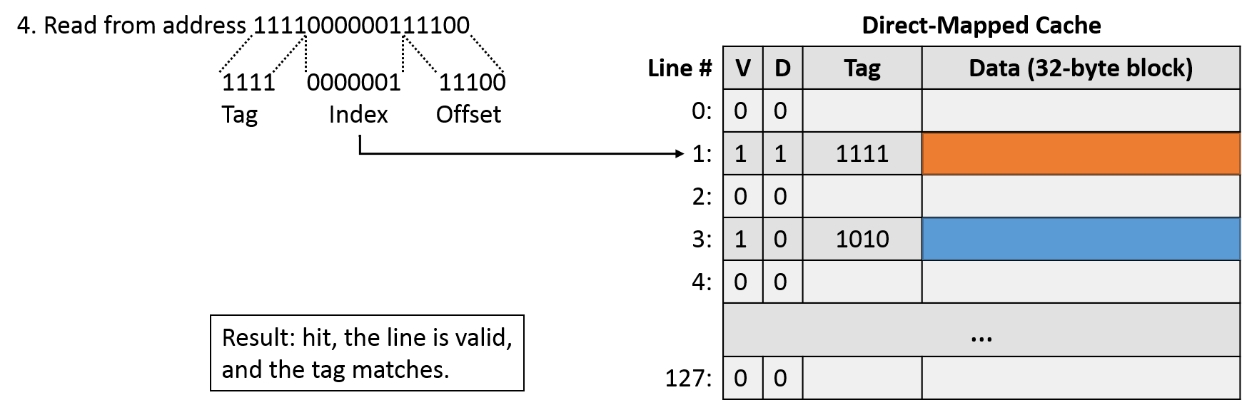
The simplest cache organization that uses these fields is the direct-mapped cache. In this design, every memory address can be stored in exactly one possible location in the cache. There is no ambiguity. This is determined entirely by the index bits of the address.
To see this mechanism in action, let's watch a short video that walks through the process.
The following video from MIT OpenCourseWare provides a clear, animated explanation of how a direct-mapped cache uses the address fields to handle a memory request.
Please watch from the beginning to 03:29. The video will cover: The basic hardware and mapping (00:00 - 00:34) The roles of the index, tag, and valid bit (00:34 - 01:30) How an address is divided into offset, index, and tag fields (01:56 - 03:29)
To solidify this, let's walk through the lookup process step-by-step:
- The CPU requests data at a certain memory address.
- The cache hardware extracts the index bits from the address.
- It uses this index to go directly to one specific cache line.
- It checks the line's valid bit. If it's 0, it's a cache miss. The data isn't here.
- If the valid bit is 1, it compares the tag bits from the address with the tag stored in the cache line.
- If the tags do not match, it's a cache miss (a conflict miss, specifically). The cache line is occupied by data from a different memory location that happens to have the same index.
- If the tags match, it's a cache hit! The requested data is in the cache. The hardware then uses the offset bits from the address to select the specific bytes from the data block and sends them to the CPU.
Practical Calculation: Dividing the Address
Being able to calculate the size of the tag, index, and offset fields is a fundamental skill in computer architecture. It reinforces your understanding of how the cache's dimensions (total size, line size) dictate its operation.
Let's use a clear, step-by-step guide to master this calculation.
How to Calculate the Number of Tag, Index, and Offset Bits of Different Caches
The Baeldung article 'How to Calculate the Number of Tag, Index, and Offset Bits' provides a very straightforward recipe for these calculations. We'll focus on the direct-mapped cache section.
Please read sections 2 ('Understanding Cache Organization Fundamentals') and 3 ('Direct-Mapped Cache Calculations'). These sections will walk you through the logic and provide concrete examples.
Let's apply this with a new example. Assume we have a system with:
- 32-bit memory addresses
- A direct-mapped cache with a total size of 32 KB (Kilobytes)
- A cache line size of 64 bytes
Let's calculate the T-I-O fields:
-
Offset Bits: The line size is 64 bytes. To uniquely address each byte, we need bits. So, the offset is 6 bits.
-
Index Bits:
- First, find the number of cache lines:
- To uniquely address each of the 512 lines, we need bits. So, the index is 9 bits.
- First, find the number of cache lines:
-
Tag Bits: The tag is whatever is left over from the total address width.
So, for any 32-bit memory address on this machine, the cache hardware will interpret it as:
| Tag (17 bits) | Index (9 bits) | Offset (6 bits) |
|---|
A Glimpse Beyond: Set-Associative Caches
The direct-mapped approach is simple and fast, but it has a weakness: conflict misses. If a program frequently alternates between two different memory locations that happen to map to the same index, they will constantly evict each other from the cache, even if the rest of the cache is empty.
To solve this, most modern CPUs use set-associative caches. This design is a compromise. Instead of mapping an address to a single line, the index maps to a set of several lines (e.g., a 2-way, 4-way, or 8-way set). The data can be placed in any of the lines within that set.
When looking for data, the cache uses the index to find the correct set and then compares the tag against all lines in that set simultaneously. This dramatically reduces conflict misses.
11.4. CPU Caches - Dive Into Systems
Let's read a short introduction to the concept of set-associative caches to understand how they differ from the direct-mapped design.
Please read the first three paragraphs of section '11.4.3. Set Associative Caches'. This will explain the high-level concept and how it serves as a middle ground between direct-mapped and fully associative caches.
The logic for dividing the address is very similar, with one key change: the index bits are now used to select a set, not a single line. This means the number of index bits depends on the number of sets.
- Number of Sets = Total Lines / Associativity (N)
- Index Bits =
This change means that for a cache of the same total size, a more associative cache will have fewer sets, requiring fewer index bits and leaving more bits for the tag.
Conclusion
In this lesson, we opened the black box of the CPU cache to understand its internal mechanics. We saw how a simple hardware design can efficiently store and retrieve data by intelligently partitioning memory addresses.
Key Takeaways:
- Data is moved between memory and cache in fixed-size cache lines (or blocks) to leverage spatial locality.
- A memory address is divided into three fields: Offset (byte within a line), Index (which line/set to check), and Tag (verification).
- A direct-mapped cache is the simplest organization, where each memory address maps to exactly one cache line, determined by the index.
- A cache lookup succeeds (a hit) only if the line is marked as valid and the address tag matches the stored tag.
- Set-associative caches improve on the direct-mapped design by allowing an address to map to any one of N lines within a set, reducing conflict misses.
Preview of the Next Lesson:
We've now seen two ways to organize a cache: direct-mapped and set-associative. In the next lesson, we will formalize this spectrum. We will compare direct-mapped, set-associative, and fully-associative cache organizations, analyzing the trade-offs between hit rate, hardware complexity, and speed for each design.