Hello! Welcome to your next lesson in the UK electrical grids course.
In previous lessons, we've established the key technical challenges that distributed generation (DG) poses for distribution networks. We started by looking at how DG can cause voltage rise, then we examined how it can disrupt protection schemes, and most recently, we saw how it can lead to thermal overloads of cables and transformers.
Today, we will circle back to the first of these challenges and explore the solutions. The learning outcome for this lesson is to describe voltage regulation techniques used in distribution networks to manage voltage issues.
We will cover the main tools and methods that Distribution Network Operators (DNOs) use to keep voltage within the legally required limits, especially in networks with a high amount of DG.
The techniques fall into two main categories:
- Mechanical Regulation: Physically adjusting transformer settings.
- Electrical Regulation: Managing reactive power flow in the network.
1. Why Voltage Control is Essential
Before we dive into the solutions, let's quickly recap why maintaining a stable voltage is so critical.
Methods of voltage control in power system
This article from Electrical Easy provides a concise explanation of why voltage needs to be kept within a specific range.
Please read the first section, titled 'Why do we need to control voltage?'. It's just two paragraphs.
As you just read, all electrical equipment is designed to operate at a specific voltage. Significant deviations can cause damage or malfunction. In the UK, DNOs have a statutory obligation to keep the voltage supplied to customers within ±10% of the nominal 230V (i.e., between 207V and 253V).
As we learned previously, reverse power flow from DG can push the voltage above this upper limit, creating an "overvoltage" problem. Now, let's look at the primary tool used to combat this at the substation level.
2. Technique 1: On-Load Tap Changers (OLTCs)
The most direct way to regulate voltage is by adjusting the transformer itself. Transformers in primary and distribution substations are often equipped with a device that can change the transformation ratio while the transformer remains energized and supplying load. This device is called an On-Load Tap Changer (OLTC).
MV/LV transformers with on-load tap changer (OLTC)
The following article from Alterga frames OLTCs specifically as a solution to the voltage problems caused by modern distributed generation, which is exactly our focus.
Please read the introduction and the sections 'Construction and operation of OLTC transformers' and 'Application of OLTC transformers'. Focus on understanding why OLTCs are more suitable than older 'off-load' tap changers for managing networks with lots of renewables.
The core principle is simple: a transformer's voltage ratio is determined by the ratio of turns in its primary and secondary windings. By adding or removing turns from a winding, you can change the output voltage. An OLTC is a mechanical switch that does this automatically without interrupting the power supply.
To see how this mechanism works, let's watch a short video.
This video from saVRee provides a clear, practical explanation of the internal workings of an OLTC.
Watch from the beginning until 03:45. The first part (up to 02:07) explains the basic principle of changing the turns ratio to regulate voltage. The second part discusses the engineering challenge of doing this 'on-load' without causing a short circuit or an interruption.

How does this solve the DG problem?
Imagine a rural network with a large solar farm.
- At night (no solar): The network has a normal load, and voltage drops slightly along the line. The OLTC might be at a 'neutral' or slightly 'voltage boosting' tap position.
- Midday (high solar, low load): The solar farm exports a large amount of power. Voltage at the far end of the network starts to rise towards the statutory limit. A voltage sensor detects this rise and sends a signal to the OLTC controller.
- The OLTC acts: It automatically moves to a different tap to lower the substation's output voltage, counteracting the rise caused by the solar farm and keeping the entire network within limits.
3. Technique 2: Reactive Power Compensation
The second major method of voltage control is more subtle. It involves managing a different kind of power on the grid: reactive power. You may recall from Module 1 that real power (measured in Watts) does useful work, while reactive power (measured in VARs) sustains the electric and magnetic fields needed by many devices.
Crucially, the flow of reactive power is intimately linked to voltage levels.
- Injecting reactive power into a network tends to increase voltage.
- Absorbing reactive power from a network tends to decrease voltage.
Let's watch an excellent explanation of this concept and the devices used to manage it.
The Most Confusing Part of the Power Grid
This video from the Practical Engineering channel is one of the best introductions to reactive power and its practical impact on the grid, including its role in voltage control.
Please watch from 06:07 to 19:32. This covers three key areas: (06:07 - 13:13) An introduction to reactive power and why it matters. (13:13 - 15:48) How reactive power affects voltage stability (the 'PV curve'). (15:48 - 19:32) The specific devices used to manage reactive power and support voltage.
Based on the video and supplementing with our other resources, let's break down the key devices used in distribution networks.
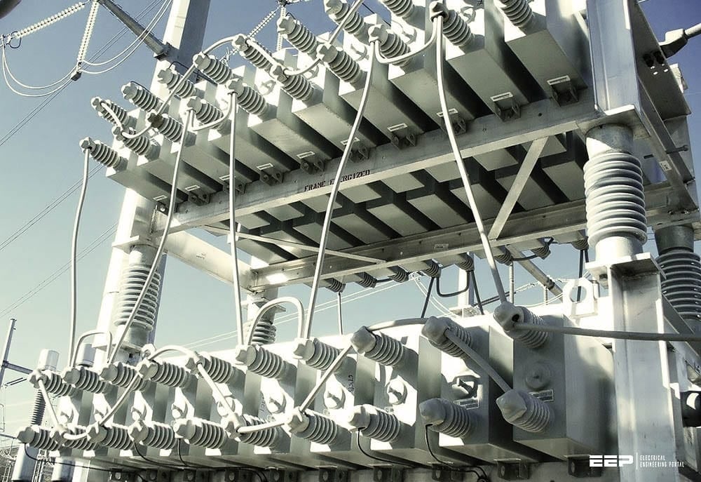
A. Shunt Capacitors
Capacitors are devices that, when connected to an AC grid, act as sources of reactive power. They are the most common and cost-effective tool for voltage support.
- Function: They "inject" reactive power, which boosts voltage.
- Application: Traditionally used to counteract the voltage drop caused by heavy inductive loads (like motors). In a network with high DG, they must be used carefully. Leaving a capacitor bank switched on during a period of high solar generation could make an overvoltage problem even worse. For this reason, they are often switched, meaning the DNO can connect or disconnect them from the grid as needed.
B. Shunt Reactors
Reactors are the opposite of capacitors. They are essentially large coils (inductors) that absorb reactive power.
- Function: They "absorb" reactive power, which lowers voltage.
- Application: They are the perfect tool to counteract voltage rise. When DG is causing voltage to become too high, the DNO can switch in a shunt reactor to absorb reactive power and pull the voltage back down into the acceptable range.
C. Advanced and Dynamic Devices
While switched capacitors and reactors are effective, they are "binary" (either on or off). For situations requiring smoother, faster, and more precise control, more advanced power electronic devices are used.
- Synchronous Condensers: As the video explained, these are essentially large synchronous motors running with no mechanical load. By varying the magnetic field in the motor, they can be controlled to either generate or absorb reactive power in a smooth, continuous fashion.
- Static VAR Compensators (SVCs): These use power electronics to rapidly switch capacitor and reactor banks in and out of the circuit. This allows for very fast and precise reactive power control to respond to fluctuating conditions, like those caused by variable wind or solar generation.
These advanced devices are more expensive and are more common on the high-voltage transmission system, but their use in distribution networks is growing as more renewables are connected.
Conclusion
In this lesson, we have explored the primary techniques that network operators use to manage voltage. These are the solutions to the voltage rise problem introduced by Distributed Generation.
Key Takeaways:
- Voltage must be kept within a strict statutory range (e.g., 207V-253V in the UK).
- On-Load Tap Changers (OLTCs) are mechanical devices on transformers that adjust the turns ratio to raise or lower voltage without interrupting supply. They are a DNO's first line of defense.
- Reactive Power Compensation is the second key method. Injecting reactive power raises voltage, while absorbing it lowers voltage.
- Shunt Capacitors inject reactive power to boost voltage.
- Shunt Reactors absorb reactive power to lower voltage.
- Advanced devices like Synchronous Condensers and SVCs provide faster and more dynamic reactive power control for more challenging situations.
We have now covered the three main technical challenges of DG integration—voltage rise, thermal limits, and protection disruption—as well as the solutions for the first two.
In the next lesson, we will complete this topic by looking at the final challenge in more detail: Describe the impact of distributed generation on network protection schemes, fault levels, and system safety.