Hello! Welcome to the second lesson in your course on UK electrical grids.
In our first lesson, we established the fundamental concepts of Alternating Current (AC), including sine waves, frequency, phase angle (), and impedance. The key takeaway was that while resistors oppose current, reactive components like inductors and capacitors also oppose current but do so by causing a phase shift between the voltage and current waveforms.
Today, we will see the direct consequence of that phase shift.
Lesson 2: Real, Reactive, and Apparent Power
Learning Outcome: By the end of this lesson, you will be able to calculate real power, reactive power, and apparent power in single-phase AC circuits.
We will explore:
- Why power in AC circuits isn't a single, simple value.
- The definitions of Real Power (P), Reactive Power (Q), and Apparent Power (S).
- The units used for each type of power: Watts (W), Volt-Amps Reactive (VAR), and Volt-Amps (VA).
- The relationship between these three types of power, known as the Power Triangle.
- How to calculate each of these values in a practical circuit.
1. Power in AC Circuits: It's Not So Simple
In a simple DC circuit, power is just voltage times current (). In AC circuits, it's more complicated. The phase shift between voltage and current, caused by reactance, means that not all the power delivered by the source is actually consumed by the load to do useful work.
To understand this, let's start with a circuit with no phase shift and then see what happens when we introduce one.
Power factor explained | Active Reactive Apparent Power correction
This video from Prof MAD provides an excellent step-by-step explanation. We'll start with the section on a simple resistive circuit, where voltage and current are in phase.
Please watch from 00:40 to 02:44. Notice how in a purely resistive circuit, the power is always positive, meaning it's always flowing from the source to the load.
As the video showed, when voltage and current are perfectly in phase (), the power is always positive. All the energy sent by the source is consumed by the load (e.g., turned into light and heat by the light bulb).
Now, let's see what happens when we add an inductor, which as we learned last lesson, causes the current to lag behind the voltage.
Power factor explained | Active Reactive Apparent Power correction
Continuing with the same video, this next section introduces an inductor and shows how the phase lag creates moments of 'negative power'.
Please watch from 02:44 to 07:17. Focus on the concept that negative power means energy is being returned to the source from the inductor's magnetic field. This returned energy does no useful work.
This "sloshing" of energy back and forth between the source and the load's reactive components (inductors and capacitors) is the key to understanding the different types of power in an AC system.
2. The Three Types of Power
Because some power does useful work and some is just stored and returned, we need three distinct terms to describe what's happening.
A very popular and intuitive way to understand these three types of power is the "beer analogy".
Power Factor Explained - The basics what is power factor pf
This video from The Engineering Mindset explains the concepts using a simple analogy.
Watch from 00:50 to 02:03. This will give you a strong intuitive model for the three types of power before we look at the formal definitions.
Now let's formally define these concepts, using the proper terminology and units.
Power factor explained | Active Reactive Apparent Power correction
Let's return to the first video for the formal definitions and units for our three types of power.
Watch from 09:07 to 11:40. Pay close attention to the names, symbols, and units for each type of power.
To summarize:
-
Real Power (P): This is the "useful" power that performs actual work, like creating light, heat, or rotating a motor. It is the beer in our analogy.
- Unit: Watt (W) or kilowatt (kW).
-
Reactive Power (Q): This is the power that oscillates back and forth, sustaining the electric and magnetic fields required by reactive components. It does no useful work but is necessary for many devices to operate. It is the foam in our analogy.
- Unit: Volt-Ampere Reactive (VAR) or kilovar (kVAR).
-
Apparent Power (S): This is the total power that the grid infrastructure (wires, transformers) must be able to carry. It's the vector sum of Real and Reactive power. It is the entire glass of beer and foam.
- Unit: Volt-Ampere (VA) or kilovolt-ampere (kVA).
3. The Power Triangle and Calculation Formulas
Real power, reactive power, and apparent power are related to each other through a right-angled triangle, often called the Power Triangle. This is the most important tool for understanding and calculating power in AC circuits.
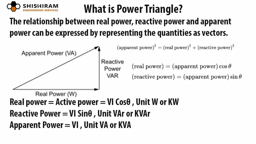
From this triangle, we can see the relationships using basic trigonometry and the Pythagorean theorem. Please read the following short text which lays out the mathematics clearly.
What is AC Power? Active Power, Reactive ...
This article from ROHM clearly explains the mathematical relationship between the three power types based on the power triangle.
Please read the section titled 'Apparent Power, Active Power, and Reactive Power'. Focus on how the Pythagorean theorem (S² = P² + Q²) is derived from the individual power formulas.
This gives us our fundamental set of formulas. For a circuit with RMS voltage , RMS current , and a phase angle between them:
-
Apparent Power (S): This is the simplest calculation, as it ignores the phase angle.
-
Real Power (P): This is the component of Apparent Power that is in phase with the voltage.
-
Reactive Power (Q): This is the component that is 90 degrees out of phase.
And the relationship between them is:
4. Worked Example: Calculating Power for a Motor
Let's apply these formulas to a practical example. An electric motor is a common inductive load, meaning it has both resistance and inductance, and will therefore consume both real and reactive power.
The following video walks through a full calculation for a single-phase motor. It starts with the basic electrical properties (resistance and inductance) and calculates everything from there.
Power factor explained | Active Reactive Apparent Power correction
This final clip from the 'Prof MAD' video provides a detailed, step-by-step calculation for an inductive motor. This brings together everything from this lesson and the previous one.
Watch from 15:13 to 18:36. Follow the steps carefully. You will see how impedance (Z) and reactance (X) from the last lesson are used to find the current and phase angle, which are then used to find the different types of power.
Let's recap the key results from that calculation:
- Given: Voltage = 120V, Frequency = 60Hz, Resistance (R) = 60 , Inductance (L) = 160 mH.
- Step 1: Calculate Reactance & Impedance. The video first calculates the inductive reactance () and then the total impedance ().
- Step 2: Calculate Current. Using Ohm's law for AC, .
- Step 3: Calculate Power.
- Apparent Power (S): Calculated as .
- Real Power (P): Calculated as .
- The video found that for an apparent power of 338 VA, the real power was only 238.5 W. The rest is reactive power.
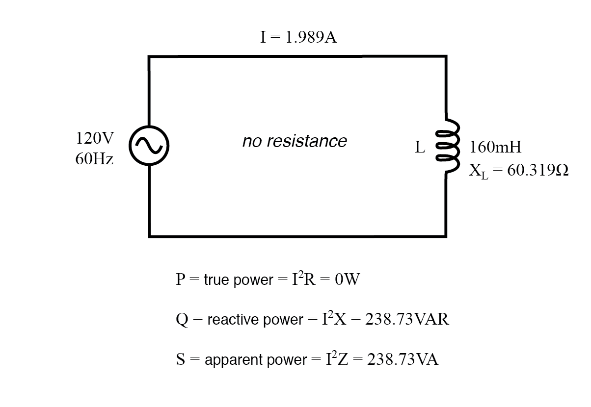
To see an extreme case, consider a load with only reactance and no resistance.
Lesson Summary
Key Takeaways:
- The phase shift between voltage and current in AC circuits leads to three distinct types of power.
- Real Power (P) is the energy consumed to do useful work, measured in Watts (W).
- Reactive Power (Q) is the energy stored and returned by reactive components, measured in Volt-Amps Reactive (VAR).
- Apparent Power (S) is the total power that must be supplied by the grid, measured in Volt-Amps (VA).
- These three are related by the Power Triangle, with the core formula being .
- The fundamental calculation formulas are:
Next Lesson Preview
You might have noticed that the grid has to supply the full Apparent Power (S), even though only the Real Power (P) does useful work. The ratio between these two () is a measure of how efficiently the power is being used. This ratio is called the Power Factor.
In our next lesson, we will explain the role of power factor in AC systems and its impact on grid efficiency. We will see why a low power factor is undesirable and what can be done to improve it.