Hello! Welcome to the first lesson in your course on UK electrical grids.
This course is designed to take you from the fundamental principles of electricity all the way to the complex details of how the UK's power system is structured, operated, and regulated.
Today, we'll start with the absolute basics. Our goal is to build a solid foundation for all the topics that will follow.
Lesson 1: AC Power Fundamentals
Learning Outcome: By the end of this lesson, you will be able to explain the concepts of alternating current (AC), including sine waves, frequency, phase angle, and impedance.
We will cover:
- What Alternating Current (AC) is and how it's generated.
- How we describe AC using concepts like sine waves, amplitude, and frequency.
- What phase angle means and why it's important.
- The concept of impedance, the unique form of "resistance" in AC circuits.
Let's begin.
1. What is Alternating Current (AC)?
The electricity that powers our homes, businesses, and industry is a specific type called Alternating Current, or AC. As the name suggests, the key feature of AC is that the flow of electrical charge periodically reverses direction. This is different from Direct Current (DC), like that from a battery, where the charge flows in only one direction.
To get a clear picture of what this means and how it's produced, please watch the first few sections of the following video.
AC Basics: Learn All About Alternating Current
This video from The Engineering Mindset provides a great visual introduction to AC. It uses a simple analogy to explain the concept and shows how a basic generator produces alternating current.
Please watch from the beginning until 01:35. Focus on how the rotation of the magnet creates a current that flows back and forth, and how this motion translates into a specific wave pattern.
As the video showed, a simple generator (or alternator) with a rotating magnet and a coil of wire will naturally produce a voltage that smoothly rises and falls, pushing and pulling electrons first one way, then the other. When we plot this voltage over time, we get a characteristic shape called a sine wave.

2. The Language of AC: Sine Waves, Frequency, and Amplitude
To work with AC, we need a precise way to describe these sine waves. We use three key parameters:
- Amplitude (Peak Voltage): This is the maximum voltage the wave reaches in either the positive or negative direction. It tells us the "strength" or "intensity" of the voltage.
- Frequency: This is the number of full cycles the wave completes in one second. The unit for frequency is Hertz (Hz). In the UK and most of the world, the grid operates at a standard frequency of 50 Hz. This means the current alternates back and forth 50 times every second.
- Period (T): This is the time it takes to complete one full cycle. It's the inverse of frequency: . For a 50 Hz system, the period is seconds.
Mathematical Description
While pictures are helpful, engineers use a standard mathematical formula to describe an AC voltage waveform precisely. The video below explains this formula and clarifies the important difference between the frequency you hear about (like 50 Hz) and the "angular frequency" used in the equation.
02 - Sinusoidal AC Voltage Sources in Circuits, Part 1
This video from the Math and Science channel breaks down the standard equation for an AC voltage. It will introduce you to the terms engineers use to describe these waves.
Please watch from 07:06 to 19:42. Pay close attention to the breakdown of the formula V(t) = Vm cos(ωt + Φ) and the explanation of frequency (f) versus angular frequency (ω).
Let's summarize the key takeaways from that video.
An AC voltage at any given time can be described by the equation:
Where:
- is the Amplitude (or peak voltage), measured in Volts (V).
- (omega) is the Angular Frequency, measured in radians per second (rad/s). It's related to the standard frequency by the formula . For the UK's 50 Hz grid, rad/s.
- (phi) is the Phase Angle, which we will discuss next.
3. Phase Angle: The Timing of Waves
In a power system, we often have multiple AC voltage and current waveforms at the same time. The phase angle describes the timing relationship between them. If two waves are "in phase," their peaks and zero-crossings happen at the same time. If they are "out of phase," one is delayed relative to the other.
We measure this shift in degrees, where one full cycle is 360°.
- A waveform that is "ahead" of another is said to be leading.
- A waveform that is "behind" another is said to be lagging.
The image below shows some common phase shifts.
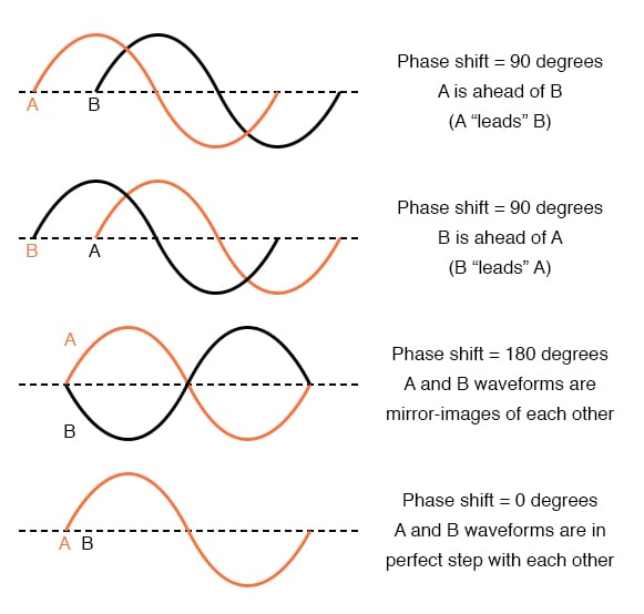
This concept of a time shift is what the in our AC voltage equation represents. It tells us how much the wave is shifted from a reference point (which is usually the main voltage source, defined as having ).
The phase difference between voltage and current is extremely important in AC circuits, as it directly affects how power is delivered. We'll explore this in the next lesson.
4. Impedance: Opposition to AC Current
In DC circuits, the opposition to current flow is called resistance (R). In AC circuits, the situation is more complex. The total opposition to current flow is called impedance (Z).
Impedance has two parts:
- Resistance (R): This is the same as in DC circuits. It's caused by the material of the wires and components, and it dissipates energy as heat.
- Reactance (X): This is an additional opposition to current that only exists in AC circuits. It's caused by components that store energy in magnetic fields (coils, or inductors) or electric fields (capacitors). Reactance doesn't consume energy but causes the current and voltage to go out of phase with each other.
To understand these concepts more formally, please read the following sections from the provided article.
AC Circuits: Alternating Current, Waveforms, and Formulas
This article from ROHM Semiconductor provides clear, concise definitions for impedance and its components.
Please read the sections titled 'Impedance' and 'Electrical Impedance in AC Circuits'. Focus on understanding that impedance (Z) is a combination of resistance (R) and reactance (X), and that inductors and capacitors are the sources of reactance.
As the text explains, impedance is represented mathematically as .
Don't worry too much about the math with "j" for now. The key concept is that resistance and reactance are two different kinds of opposition that combine to give the total impedance.
- Resistors only have resistance. In a purely resistive circuit, voltage and current are in phase.
- Inductors and Capacitors only have reactance. They cause a 90° phase shift between voltage and current (in opposite directions).
- Real-world AC circuits contain a mix of all three, resulting in an impedance that has both resistance and reactance, and a phase shift somewhere between 0° and 90°.
Lesson Summary
Congratulations on completing your first lesson! This was a dense but essential introduction to the language of AC power.
Key Takeaways:
- Alternating Current (AC) is an electrical current that periodically reverses direction, following a sine wave pattern in power systems.
- AC waveforms are described by their Amplitude (peak value), Frequency (cycles per second, 50 Hz in the UK), and Period (time for one cycle).
- The Phase Angle () describes the timing shift between different AC waveforms, measured in degrees.
- Impedance (Z) is the total opposition to current in an AC circuit. It is a combination of Resistance (R), which dissipates energy, and Reactance (X), which stores energy and causes phase shifts.
Next Lesson Preview
In the next lesson, "Calculate real power, reactive power, and apparent power in single-phase AC circuits," we will build directly on what we've learned today. You'll see how the impedance of a circuit and the phase angle between voltage and current determine the different types of power that are consumed and transferred in the grid.