Hello! Welcome to the next lesson in your hydraulic design journey.
In our last session, we calculated the total friction loss along the main and lateral pipes for a full irrigation zone. We used a simple 10% estimate to account for fittings. Today, we're going to replace that estimate with precise calculations. Our goal is to accurately determine the pressure lost by every component the water passes through, from the water meter at the source to the valves and fittings in the pipe network.
This is a crucial step. In the complex, compact layouts typical of villa gardens, these "minor" losses from components can add up to be a major factor in your system's performance.
1. The Two Types of Pressure Loss: Frictional and Minor
As water moves through your system, it loses pressure in two ways:
- Frictional Loss: Caused by friction between the water and the inside walls of the pipes. We covered how to calculate this in the last two lessons.
- Minor Loss: Caused by the turbulence created when water changes direction or passes through an obstruction. This happens in every elbow, tee, valve, filter, and water meter.
This image provides a great visual summary of the two loss types and a glossary of the common fittings that cause minor losses.
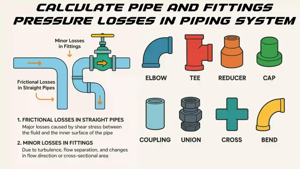
While called "minor," these losses are anything but. In long, straight agricultural pipelines, pipe friction dominates. But in the tight network of a residential or commercial landscape, with numerous turns and components, minor losses can account for a significant portion of the total pressure drop.
2. How to Quantify Minor Losses
Manufacturers provide performance data for their components, which allows us to calculate the pressure loss. There are two common methods you'll encounter:
- Direct Pressure Loss: For major components like valves, filters, and water meters, manufacturers provide charts that state the exact pressure loss (in PSI or Bar) for a given flow rate (GPM or L/h).
- Equivalent Length Method: For pipe fittings like elbows and tees, the turbulence they create is quantified as being equivalent to a certain length of straight pipe. For example, the pressure loss through a 1-inch, 90-degree elbow might be equivalent to the loss in 2.7 feet of 1-inch pipe.
Let's explore how to use both. We'll rely on industry-standard friction loss charts, which are an essential tool for any irrigation designer.
To begin, please download and save these Friction Loss Tables from Hunter Industries. This document is a comprehensive reference that you will use throughout your career. For this lesson, we will focus on the tables for specific components.
Download this PDF and have it open. We will be referring to several tables within it. Familiarize yourself with the layout, particularly the tables for: PRESSURE LOSS THROUGH WATER METERS (page 10) PRESSURE LOSS THROUGH BRONZE GATE VALVES (page 10) PRESSURE LOSS THROUGH SWING CHECK VALVES (page 9) PRESSURE LOSS IN VALVES AND FITTINGS (Equivalent Length, page 9)
3. Calculating Loss from Major Components
Let's start with the easy one: direct pressure loss from manufacturer charts. This applies to components that are installed along your main line before the water is split into zones.
Water Meters
Every municipal water source will have a water meter. The water rushing through it creates friction and loses pressure.
- How to find the loss: Open your saved
Friction Loss TablesPDF to page 10. Find the table titled "PRESSURE LOSS THROUGH WATER METERS". - Example: If your villa's zone requires 20 GPM and the site has a 1" water meter, you can see the pressure loss is 3.8 PSI.
Valves, Filters, and Backflow Preventers
Every other major component (zone valves, master valves, filters, backflow preventers) also has a pressure loss value that you must get from its specific manufacturer's performance chart. These are typically listed in the product's technical specifications.
- Zone Valve Loss: In the sample problem from our previous lesson, the Hunter PGV valve had a loss of 4.3 PSI at 30 GPM.
- Filter Loss: A filter manufacturer will specify pressure loss. For example, a spec sheet might say "5 PSI loss at 25 GPM". Important: Filters get clogged with debris over time, which increases pressure loss. For conservative design, it's wise to use the "dirty filter" pressure loss value if the manufacturer provides it.
4. Calculating Fitting Loss: The Equivalent Length Method
For common pipe fittings, we use the "equivalent length" method. This is a more precise approach than our previous 10% estimate and is essential for accurate calculations on your most demanding zone.
The process is:
- Count all the fittings along the water's path for a specific zone.
- Use a table to find the "equivalent length" of straight pipe for each fitting.
- Sum these lengths to get a "Total Equivalent Length".
- Calculate the friction loss for this total length as if it were an actual piece of pipe.
Let's see this in action with a detailed manual.
B.C. SPRINKLER IRRIGATION MANUAL
The B.C. Sprinkler Irrigation Manual provides an excellent, clear example of calculating fitting loss using the equivalent length method. This is the core technique we are learning in this section.
Please read the section titled 'Fitting and Miscellaneous Losses' and study 'Example 8.4 Fitting Friction Loss' (page 132 of the PDF). Notice how they: List the fittings and their sizes. Use a table (in their case, Appendix Table B.10) to find the equivalent pipe length for each fitting. Calculate the friction loss for each fitting type by multiplying its equivalent length by the pipe's friction loss rate (psi per 100 ft). Sum the individual losses to get the total.
As you saw in the manual, you need the right table for your fittings. The Friction Loss Tables from Hunter (page 9) provide a table for "Standard Steel Pipe" fittings. In practice, you would find a similar table from your pipe supplier for PVC fittings. For our exercises, we will use the Hunter table while acknowledging this detail.
Test your understanding!
A main line for a villa is made of 1 1/4" PVC Schedule 40 pipe and carries 20 GPM to a sprinkler zone. Along its path, it has:
- Two 90-degree standard elbows
- One run of a standard tee (where water flows straight through)
Using the Friction Loss Tables (LINK), calculate the total pressure loss from these fittings.
Steps:
- Find the friction loss rate (PSI per 100 ft) for the pipe and flow rate (use the Sch 40 table on page 2).
- Find the equivalent length for each fitting (use the table on page 9).
- Calculate the total loss.
Show answer
-
Friction Loss Rate: From the Sch 40 table (LINK, page 2), for a 1 1/4" pipe at 20 GPM, the friction loss is 3.24 PSI per 100 ft.
-
Equivalent Lengths: From the "Equivalent Length" table (LINK, page 9), for 1 1/4" pipe size:
- Std. Elbow: 3.9 ft
- Run of Std. Tee: 2.0 ft
- Total Equivalent Length = (2 x 3.9 ft) + (1 x 2.0 ft) = 7.8 ft + 2.0 ft = 9.8 ft
-
Calculate Total Loss:
The total pressure loss from these three fittings is approximately 0.32 PSI.
Conclusion
You have now moved from rough estimations to precise calculations for component-related pressure losses. This detailed analysis ensures that the pressure you calculate is what the system will actually experience.
Key Takeaways:
- "Minor losses" from components are a major factor in residential irrigation design.
- Pressure loss for major components like water meters, valves, and filters is found directly on their manufacturer performance charts.
- Pressure loss for pipe fittings like elbows and tees is calculated using the Equivalent Length Method, where each fitting is treated as a short piece of straight pipe.
- The total pressure loss from all components is the sum of these individual calculated losses.
In our next and final lesson on hydraulics, we will add the last critical variable: elevation. You will learn how to calculate pressure gains or losses due to changes in height on the site. By combining pipe friction loss, component loss, and elevation changes, you will be able to calculate the Total Dynamic Head (TDH), the single most important number for determining if your water source is adequate or if a pump is needed.