Hello! Welcome to your lesson on summarizing friction loss for an entire irrigation zone.
In our last lesson, you mastered the foundation of hydraulics: calculating friction loss for a single segment of pipe using both charts and the Hazen-Williams formula. You now understand how pipe diameter, length, and flow rate all contribute to pressure loss.
Today, we'll put that knowledge into practice on a larger scale. We are moving from a single pipe to a complete network. You will learn how to calculate the cumulative friction loss for an entire irrigation zone, starting from the water source, going through the main line, and extending down the lateral line to the very last sprinkler. This is a critical step in verifying that your design will work efficiently in the real world.
1. Visualizing the Path of Water
Before we dive into calculations, let's look at what we're trying to analyze.
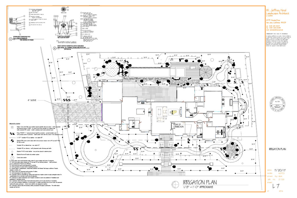
When one zone is running, water flows from the source, through the main line, through the zone valve, and then along the lateral line. Our goal is to calculate the total pressure lost to friction along this entire path.
To do this, we break the problem into three parts:
- Main Line Loss: The loss in the pipe from the water source to the zone valve.
- Lateral Line Loss: The loss in the pipe connecting all the sprinklers after the valve.
- Fitting Loss: The loss caused by turbulence in elbows, tees, and other fittings.
2. The Key Concept: Diminishing Flow in Lateral Lines
Calculating friction loss in the main line is straightforward. The flow rate is constant—it's the total flow required for all sprinklers in that one zone. You can calculate this just as you did in the previous lesson.
The lateral line is different and is the main focus of today's lesson. As water flows down the lateral line, some of it exits at each sprinkler. This means the flow rate is not constant; it diminishes after each head.
Consider a simple lateral line with three sprinklers, each using 6 Gallons Per Minute (GPM):
A simple diagram showing how flow rate decreases along a lateral line. Pipe Section A carries the flow for all three sprinklers (18 GPM), Section B carries the flow for the last two (12 GPM), and Section C carries flow only for the final sprinkler (6 GPM).
Because friction loss depends on flow rate, we cannot calculate the loss for the entire lateral line in one step. We must calculate the loss for each segment individually and then sum them up. The standard professional practice is to start from the furthest sprinkler and work your way back toward the valve.
3. A Practical Approach: Calculating Total Friction Loss
Let's combine these concepts into a step-by-step method. The most comprehensive and practical guide for this is the Hunter Irrigation System Design manual. It provides an excellent, detailed walkthrough of calculating the total friction losses for a critical zone.
We will work through its sample problem together. The process outlined here is the exact method you will use in your professional designs.
Irrigation System Design (Student Guide)
This section of the Hunter design guide is the core of today's lesson. It provides a complete, step-by-step example of how to calculate the total friction loss for an entire sprinkler zone, including the lateral line, main line, and fittings. Please study it carefully.
Please read the entire section titled 'Calculating Friction Losses' (it starts on page 33 of the PDF). Focus on the 'Sample Problem'. Follow along as the guide calculates: Lateral Line Losses: Notice how they calculate the loss for each pipe segment between sprinklers, starting from the furthest head (A) and working back to the valve. Main Line Loss: See how they use the total zone GPM (30 GPM) to calculate the loss in the main line. Fitting Losses: Pay attention to the practical shortcut used: estimating fitting loss as 10% of the total pipe loss. Valve Loss: Note how they find the pressure loss for the specific valve model from a manufacturer's chart. Total Zone Loss: Finally, observe how all these individual losses are summed up to get the final total.
4. Breakdown of the Calculation Process
Let's summarize the key steps from the Hunter guide to ensure the process is clear. You will follow these steps for any zone you design.
Step 1: Calculate Lateral Line Loss (Segment by Segment)
- Start with the last segment: The pipe between the last two sprinklers. Determine the flow (GPM of the last sprinkler), look up the PSI loss per 100 ft from your friction loss chart, and calculate the loss for that segment's length.
- Move to the next segment: Determine the new flow (GPM of the last two sprinklers combined). Look up the corresponding PSI loss rate and calculate the loss for this segment.
- Repeat: Continue this process, adding the flow of the next sprinkler and calculating the loss for each segment, until you reach the zone valve.
- Sum the results: Add up the friction loss from all lateral line segments.
Step 2: Calculate Main Line Loss
- Use the total flow rate for the entire zone.
- Use the length and size of the main line pipe.
- Calculate the friction loss for this single, continuous pipe run.
Step 3: Estimate Fitting Loss
- Sum the total friction loss from all pipes (Lateral + Main Line).
- Calculate 10% of this value. This is a widely accepted industry estimate for the pressure loss caused by fittings like elbows and tees.
Step 4: Sum All Losses for the Zone
- Total Pipe Loss = (Total Lateral Line Loss) + (Main Line Loss)
- Total Zone Friction Loss = (Total Pipe Loss) + (Fitting Loss) + (Valve Loss) + (Other Component Loss)
The value you get is the total pressure that will be lost to friction while operating that zone.
Test your understanding!
In the sample problem from the Hunter guide (LINK), the friction loss for the pipe segment between sprinklers D and E was calculated to be 1.06 PSI. This segment is 50 ft long, made of 1-1/4" Class 200 PVC, and carries the flow for 4 sprinklers (A, B, C, and D), totaling 24 GPM.
Now, imagine you change the design to use 1-inch Class 200 PVC for that same segment. Using a friction loss chart (like the one on page 47 of LINK or page 4 of the LINK PDF), what would the new friction loss be for this 50 ft segment at 24 GPM? How does it compare to the original 1.06 PSI?
(Hint: Find the row for 24 GPM, look under the 1" pipe size column for the PSI Loss per 100 ft, and then calculate for 50 ft.)
Show answer
- Find the loss rate: On a friction loss chart for Class 200 PVC, find the row for 24 GPM. In the column for 1" pipe, the PSI loss per 100 ft is approximately 4.13 PSI.
- Calculate for the segment length: The segment is 50 ft long.
The new friction loss for this single segment is ~2.07 PSI, almost double the original 1.06 PSI. This shows how critical correct pipe sizing is—a seemingly small change in diameter has a major impact on pressure loss.
Conclusion
Congratulations! You have now learned the complete, professional method for calculating the total friction loss within an irrigation zone. This is no longer an abstract concept; it is a practical, step-by-step process that you can apply directly to your designs.
Key Takeaways:
- The total friction loss in a zone is the sum of losses from the main line, the lateral lines, and components like fittings and valves.
- The flow rate in a lateral line decreases after each sprinkler, so you must calculate friction loss for each pipe segment individually and sum them up.
- The standard method is to work from the furthest sprinkler back to the zone valve.
- The flow rate in the main line is constant for any single zone and is equal to that zone's total GPM.
- A practical industry shortcut is to estimate total fitting loss as 10% of the total pipe friction loss.
In our next lesson, we will complete our hydraulic analysis. You'll learn how to account for pressure losses from all other system components (like filters and backflow preventers) and, critically, how to factor in changes in elevation. By combining all these losses, you will be able to calculate the Total Dynamic Head (TDH), which tells you the total pressure your water source must provide to make the system work.