Hello! Welcome to the first lesson in our module on Hydraulic Design.
In the previous module, you learned how to design drip zones and select specific components like filters and pressure regulators. A critical piece of information you needed for that was the zone's total flow rate.
Today, we take that flow rate and begin the journey of sizing the pipes that will carry it. We'll start with the most fundamental principle of hydraulics in irrigation: the relationship between flow rate (Q), pipe diameter (d), and water velocity (v). Understanding this concept is the first and most important step in designing a system that works efficiently and lasts a long time.
By the end of this 60-minute lesson, you will be able to explain this critical relationship and use it to make initial pipe sizing decisions.
1. The Core Relationship: Flow, Speed, and Size
At its heart, the relationship is intuitive. Imagine water flowing through a pipe. If you want to move the same amount of water through a much narrower pipe, the water will have to speed up.
This relationship is described by a simple principle: Flow Rate = Cross-Sectional Area × Velocity.

Let's break this down:
- Flow Rate (Q): The volume of water passing a point per unit of time. We've been calculating this in Liters per Hour (L/h), but for hydraulic calculations, it's often expressed in Gallons per Minute (GPM) or cubic meters per hour (m³/h).
- Pipe Diameter (d): The internal size of the pipe. The cross-sectional area is calculated from this.
- Velocity (v): The speed at which the water is moving inside the pipe, typically measured in feet per second (FPS) or meters per second (m/s).
The key takeaways from this relationship are:
- For a fixed flow rate, if you decrease the pipe diameter, the velocity will increase.
- For a fixed flow rate, if you increase the pipe diameter, the velocity will decrease.
2. Why Velocity Matters: The "Speed Limit" in Irrigation
So, why do we care about how fast the water is moving? Because excessively high water velocity is destructive to an irrigation system. It can cause:
- High surge pressures (water hammer): When valves close quickly, the fast-moving water slams to a halt, creating a shockwave that can burst pipes and break fittings.
- Scrubbing/Erosion: High-speed water can literally wear away the inside of pipes and fittings, especially at bends (elbows), leading to premature failure.
- High Friction Loss: As velocity increases, the friction between the water and the pipe walls increases dramatically. This friction causes pressure to drop, which we will explore in detail in the next lesson.
To prevent these issues, the irrigation industry has a crucial rule of thumb:
The velocity of water in irrigation pipes should not exceed 5 feet per second (FPS), which is approximately 1.5 meters per second (m/s).
To understand why this is so important, let's watch a short video.
How to Size an Irrigation Mainline (Step-by-Step DIY Guide)
This clip from the Drip Depot channel clearly explains the consequences of getting mainline sizing wrong, emphasizing the roles of velocity and friction loss.
Watch the segment from 01:36 to 02:22. The presenter explains why both friction loss and velocity matter and what can happen if you get them wrong.
This 5 FPS "speed limit" is the guiding principle for the first step of pipe sizing. Our job as designers is to choose a pipe diameter large enough to keep the velocity below this limit for a given flow rate.
3. Sizing in Practice: Using Velocity Charts
Professionals don't guess pipe sizes; they use charts that have already done the calculations. These charts are one of the most important tools in your design toolkit. They directly show the relationship between flow rate, pipe size, and the resulting velocity.
Let's learn to read one.
PVC Schedule 40 IPS Plastic Pipe Friction Loss Chart
This friction loss chart for PVC Schedule 40 pipe from Rain Bird is an industry-standard document. It perfectly illustrates the relationship we're discussing and is a tool you will use constantly.
Please open this one-page PDF. It looks complex, but it's very logical. Find the 'Flow (gpm)' column on the far left. Find the row for 12 gpm. Follow that row to the right. Each column represents a different nominal pipe size (1/2", 3/4", 1", etc.). For each size, you'll see two sub-columns: 'Velocity (ft/s)' and 'Loss (psi)'. Notice the dark shaded area. This is a visual warning that the velocity is over 5 ft/s, making that pipe size unsafe for the corresponding flow rate.
Let's use the chart with an example.
Scenario: A sprinkler zone requires a total flow of 18 GPM.
- Find the 18 gpm row in the Rain Bird chart.
- Move right and examine the velocity for each pipe size:
- 3/4" pipe: The chart doesn't even list a value because the velocity would be extremely high.
- 1" pipe: Velocity is 6.94 ft/s. This is in the shaded "no-go" zone. The pipe is too small.
- 1 1/4" pipe: Velocity is 3.97 ft/s. This is below 5 ft/s and in the white area. This pipe size is acceptable.
- 1 1/2" pipe: Velocity is 2.90 ft/s. This is also acceptable.
For this flow rate, the smallest pipe size we can use is 1 1/4". While a 1 1/2" pipe would also work and would result in even lower friction loss (a topic for our next lesson), the 1 1/4" pipe meets our primary safety requirement for velocity.
Test your understanding!
Using the same Rain Bird chart (LINK), you have a large sprinkler zone with a total flow of 40 GPM. What is the smallest nominal pipe size you can use while keeping the velocity safely below 5 ft/s?
Show answer
- Find the 40 gpm row in the chart.
- Look across the columns for velocity:
- 1 1/4" pipe: Velocity is 8.82 ft/s (shaded, too high).
- 1 1/2" pipe: Velocity is 6.46 ft/s (shaded, too high).
- 2" pipe: Velocity is 3.89 ft/s. This is the first size that is under the 5 ft/s limit.
- Therefore, the smallest suitable pipe size for 40 GPM is 2 inches.
This same principle applies regardless of units. Here is a similar chart that uses metric units, which may be more familiar from your landscaping work.
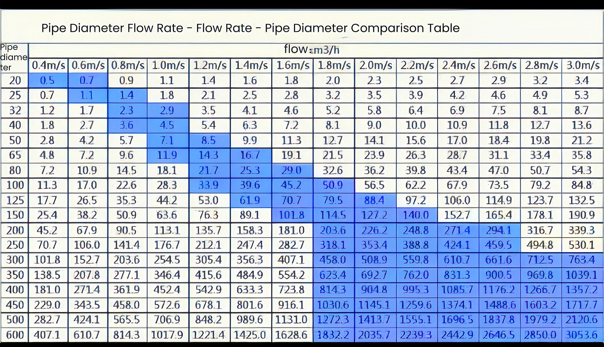
4. The Formula Behind the Charts
The charts are incredibly convenient, but they are based on a simple physics equation. Understanding it will solidify your knowledge.
PVC Schedule 40 IPS Plastic Pipe Friction Loss Chart
The velocities in the chart aren't magic. They are calculated using a standard formula that directly connects flow, velocity, and pipe diameter.
Look at the very bottom of the same Rain Bird chart PDF. You will see the formula used to calculate velocity: V = 0.408 × Qgpm / d². This is the mathematical expression of the relationship we've been exploring.
The formula is:
Where:
- is the velocity in feet per second (ft/s).
- is the flow rate in gallons per minute (gpm).
- is the actual internal diameter of the pipe in inches.
This formula mathematically confirms what we observed in the chart: velocity increases with flow rate () and decreases sharply as the pipe's internal diameter () increases.
A quick note on pipe diameters:
- PVC pipe is typically specified by its outer diameter (OD) because fittings go on the outside.
- Polyethylene (PE) pipe is typically specified by its inner diameter (ID) because fittings insert into the inside.
This means a 1" PVC pipe and a 1" PE pipe have different internal diameters and therefore different hydraulic properties. It's a small but crucial detail we will revisit.
Conclusion
Today you've learned the first and most fundamental rule of hydraulic design. You now understand the direct and critical link between the amount of water you need to move, the size of the pipe you choose, and the speed at which that water travels.
Key Takeaways:
- For a constant flow rate, a smaller pipe means higher water velocity.
- The industry standard is to keep water velocity below 5 FPS (1.5 m/s) to prevent damage from water hammer and erosion.
- Velocity charts are the primary tool used to select the minimum appropriate pipe size for a given flow rate.
- The relationship is defined by the formula , which shows velocity is directly proportional to flow rate and inversely proportional to the square of the pipe's internal diameter.
In our next lesson, we will build directly on this foundation. We'll answer the question: "Now that I've chosen a pipe size that keeps velocity safe, how much pressure will I lose due to friction?" This will lead us to defining friction loss (head loss) and its critical impact on system pressure.