Hello! Welcome to your next lesson on the Principles of Hydraulic Design.
In our last session, we established the fundamental rule for sizing pipes: keeping the water velocity below 5 feet per second (approximately 1.5 m/s) to protect the system from damage like water hammer. You learned how to use a velocity chart to find the minimum pipe diameter for a given flow rate.
We also touched on the idea that high velocity causes high friction. Today, we will explore this critical concept. This lesson addresses the learning outcome: "Define friction loss (head loss) and its impact on system pressure." We'll uncover what friction loss is, what causes it, and why it's a central challenge in every irrigation design.
1. What is Friction Loss?
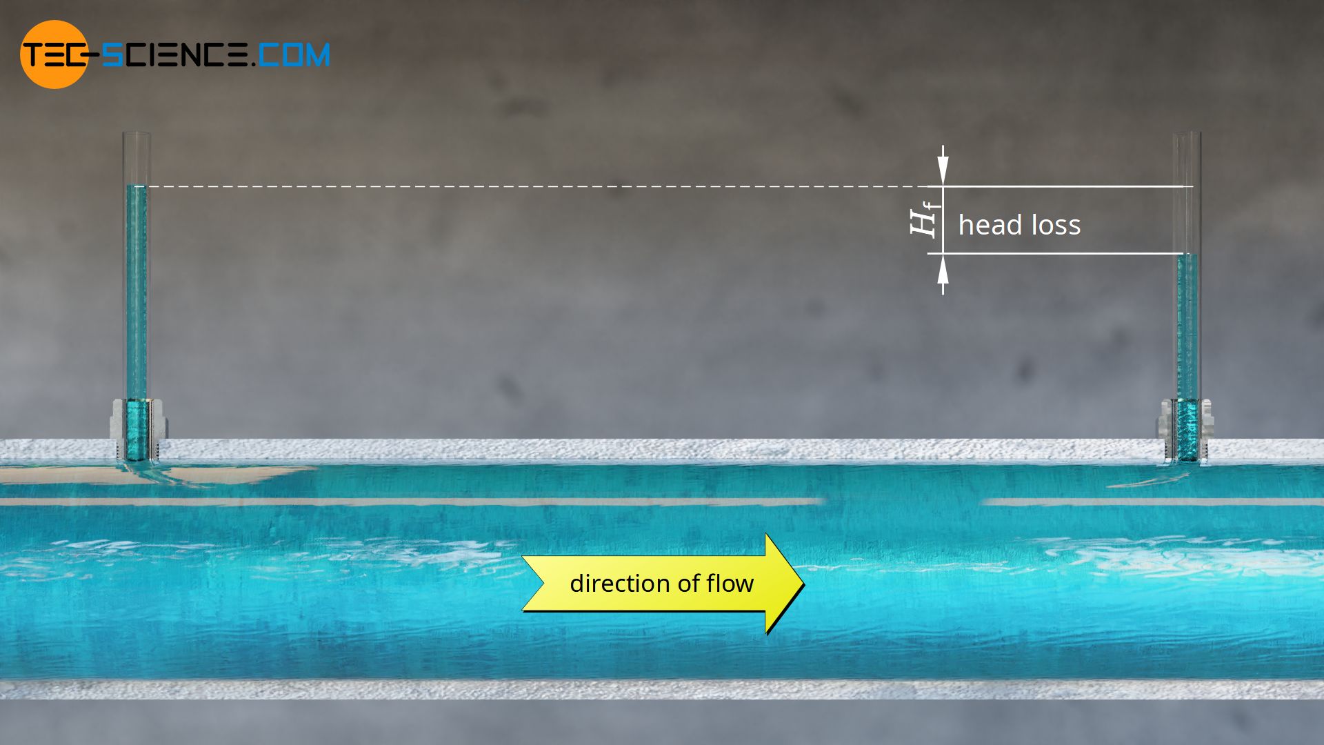
When water is stationary in a pipe, the pressure is the same everywhere (accounting for elevation). This is static pressure. However, the moment water starts to move, it encounters resistance from the inner walls of the pipe and from the turbulence of its own flow. This resistance causes the pressure to drop progressively along the length of the pipe. This drop in pressure is called friction loss or head loss.
Think of it as a "pressure tax" you pay for every meter of pipe the water travels through.
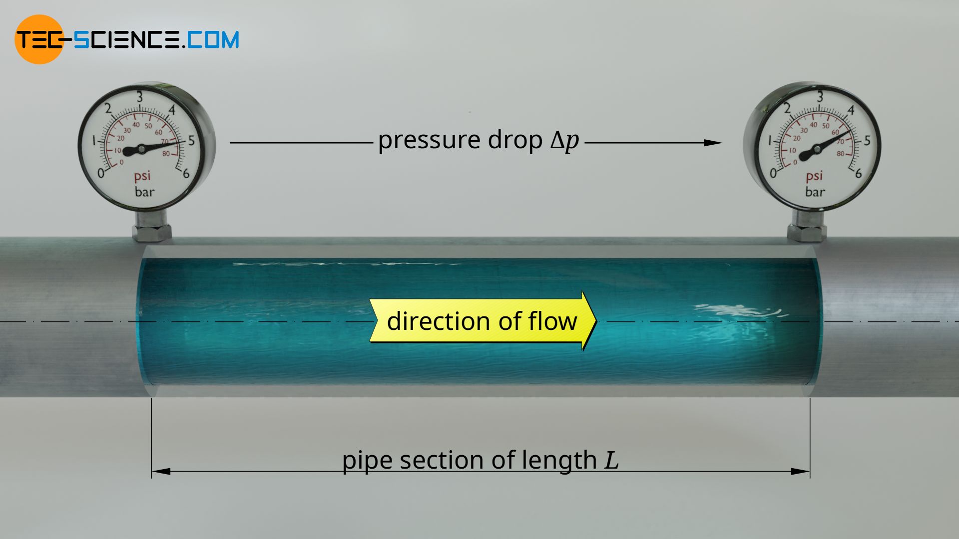
The term "head loss" comes from a more visual way of thinking about pressure. "Head" refers to the height of a column of water that would create a certain pressure. So, a loss of pressure can be visualized as a loss of height, or "head."
2. The Causes of Pressure Loss: A Practical Overview
To get a solid grasp of this concept, let's watch a video that explains and demonstrates the core principles of pressure loss in pipes.
Flow and Pressure in Pipes Explained
This video from the Practical Engineering channel provides an excellent, intuitive explanation of pressure loss. Pay close attention to the analogy with electrical circuits and the term 'turbulence'.
Watch from the beginning to 03:15. The host introduces the problem of pressure loss, draws an analogy to electrical resistance, and then explains his test setup for measuring what he calls 'head loss'.
As the video explains, pressure loss is not random. It is a predictable outcome based on four key factors related to the pipe itself, plus the system's components.
3. The Four Factors of Pipe Friction
The amount of pressure lost in a straight run of pipe depends on four things. Let's watch the video's demonstration and then look at a more formal definition.
Flow and Pressure in Pipes Explained
Now, let's see how two of these factors—pipe length and diameter—have a dramatic and measurable effect on head loss. The demonstrations in this clip make the concepts very clear.
Watch the segment from 04:03 to 06:17. Observe how the measured head loss changes when a much longer pipe is used, and then when a smaller diameter pipe is used.
The video provides a great visual, and the following resource breaks down all four factors with clear explanations and diagrams.
For a detailed breakdown, let's turn to the 'Irrigation Hydraulics' instructor manual from Hunter Industries. This section provides a classic, clear explanation of the four factors that determine friction loss.
Please find and read the section titled 'Friction loss in pipe' (it appears on page 12 of the PDF). Focus on the descriptions and the figures (Fig. 9 to Fig. 12) for each of the four factors: velocity, inside diameter, roughness, and length.
To summarize the relationships you just studied:
| Factor | Change | Effect on Friction Loss | Why? |
|---|---|---|---|
| Length | Increases | Increases | The "pressure tax" is applied over a longer distance. |
| Diameter | Decreases | Increases (dramatically) | For the same flow, water velocity increases, and more of the water is in contact with the pipe wall, creating more friction. |
| Velocity | Increases | Increases (dramatically) | Faster water creates much more turbulence and friction. |
| Roughness | Increases | Increases | A rougher inner pipe wall creates more turbulence. (e.g., old steel pipe vs. smooth PVC). |
4. Minor Losses: The Cost of Bends and Fittings
Friction loss doesn't just happen in straight pipes. Every time the water has to change direction or pass through a component, it creates extra turbulence, which causes an additional drop in pressure. These are called minor losses.
In landscape irrigation, with its many turns and components, these "minor" losses can add up to be quite significant.
Flow and Pressure in Pipes Explained
The pipe itself isn't the only source of pressure loss. This part of the video explains 'minor losses' from fittings like elbows and valves.
Watch from 06:50 to 08:34. The host explains why a turn causes turbulence and demonstrates the measurable effect of adding bends to a pipe.
Key sources of minor loss in an irrigation system include:
- Elbows and tees
- Valves (solenoid valves, ball valves)
- Water meters
- Backflow prevention devices
- Filters
As a designer, you must account for these losses in addition to the friction from the pipe itself. A common rule of thumb is to estimate the minor losses as 10-20% of the total pipe friction loss.
Test your understanding!
You are designing the pipe layout for a large lawn area. You have two options to get water to a valve manifold:
- Option A: A 25-meter route using 1" pipe that requires four 90-degree elbows to get around planting beds.
- Option B: A 35-meter route using the same 1" pipe that is a single straight run with no elbows.
Which option is likely to have lower total friction loss? Why?
Show answer
This is a classic design trade-off.
- Option B is longer, so it will have significantly more pipe friction loss than Option A.
- Option A is shorter, but it has four elbows, which will introduce minor losses that Option B does not have.
Without doing the exact calculations (which we will learn later), it's impossible to be certain. However, the pressure loss from an extra 10 meters of pipe is often greater than the loss from a few well-designed fittings. Therefore, Option A is likely to have lower total friction loss. The key takeaway is that you must consider both pipe length and the number of fittings when planning a route. Sometimes a shorter, more complex route is better than a long, simple one.
5. The Final Impact: Visualizing Total Pressure Loss
The ultimate impact of friction loss is simple: it reduces the pressure available to do work at the sprinkler head. Your design must ensure that after all losses are subtracted, there is still enough pressure for the sprinklers to operate correctly.
Operating Pressure at Sprinkler ≈ Static Pressure at Source - Pressure Change from Elevation - Pipe Friction Loss - Minor Losses
Engineers often use a diagram called a Hydraulic Grade Line (HGL) to visualize this continuous drop in pressure along a pipeline. As an architect, you may find this graphical representation very intuitive.
Flow and Pressure in Pipes Explained
To tie all this together, let's look at how engineers visualize the cumulative pressure drop along a pipeline using a hydraulic grade line.
Watch this final clip from 09:06 to 10:11. Focus on how the line on the graph steps down at each source of friction, providing a clear picture of the pressure profile.
Conclusion
In this lesson, you've moved from simply respecting a velocity limit to understanding the consequences of water movement: pressure loss.
Key Takeaways:
- Friction Loss (or Head Loss) is the reduction in pressure that occurs as water moves through pipes and fittings due to friction and turbulence.
- The primary factors influencing pipe friction are length, inside diameter, water velocity, and pipe roughness.
- Minor Losses are additional pressure drops caused by fittings, valves, and other components that create turbulence.
- The total pressure loss directly impacts your system's performance by reducing the pressure available at the sprinklers. An effective design must carefully manage these losses.
Now that you can define friction loss and explain its causes, our next lesson will make this practical. We will learn how to use industry-standard friction loss charts to determine the exact amount of pressure lost for a given pipe, flow rate, and length. This is the next step in performing a full hydraulic calculation for your irrigation zones.