Welcome to the next step in your journey from theory to practice. In our previous lessons, you've mastered the foundational laws of circuits and learned how to operate a multimeter, your essential tool for observing the physical behavior of electronics. We discussed not just how to measure, but also the engineering realities of how the meter itself interacts with a circuit, such as its input impedance.
This lesson is where it all comes together. We will focus on one of the most fundamental and widely used circuits in electronics: the voltage divider. You will learn its purpose, how to design one with a specific output, and then you'll perform the core engineering workflow: calculate the expected performance, build the physical circuit on a breadboard, and use your multimeter to test if reality matches your design. This process of design, build, and test is the bedrock of hardware engineering.
By the end of this lesson, you will be able to build a functional voltage divider, predict its output, and verify your calculations with real-world measurements, including analyzing why small discrepancies might occur.
1. What is a Voltage Divider?
At its core, a voltage divider does exactly what its name suggests: it takes a larger voltage and scales it down to a smaller one. This is an incredibly common requirement in embedded systems. For example, a battery might provide 12V, but the microcontroller you're using can only safely measure voltages up to 3.3V. A voltage divider is the simple, elegant solution to scale that 12V down into a range the microcontroller can read.
The circuit consists of just two resistors connected in series. The output voltage is "tapped" from the point between them.
To get a strong intuition for how this works, the following animated video provides an excellent visual explanation.
Voltage Divider Explained | Animated Deep Dive
This animation from Voltverse clearly illustrates the principle of voltage division.
Watch the first part of the video, from the beginning up to the end of the conceptual explanation. Focus on how the total voltage from the source is "dropped" across each of the series resistors.
As the video explains, the two resistors share the total voltage drop. The portion of the voltage dropped across each resistor is proportional to its resistance. By choosing the resistor values carefully, we can precisely control the output voltage.
2. Calculation and Design
The relationship between the input voltage, output voltage, and the two resistors is defined by the voltage divider equation. We can derive this directly from Ohm's Law.
For two resistors, and , in series, the total resistance is .
The current () flowing through the series circuit is given by Ohm's Law:
The output voltage, , is the voltage drop across resistor . Applying Ohm's Law to :
Substituting the expression for into this second equation gives us the voltage divider formula:
This elegant formula is your primary design tool. You can rearrange it to solve for any of the variables. For a deeper look at the equation and its components, you can watch the next segment of the Voltverse video.
Voltage Divider Explained | Animated Deep Dive
This part of the video formally introduces the equation we just derived and walks through an example.
Watch from this point to see the equation explained.
3. Hands-On Lab: Build, Test, and Verify
Now, let's put theory into practice. Your task is to build a voltage divider, calculate its expected output, and then measure the actual output with your multimeter. This exercise will solidify your understanding and your practical skills.
Here is an image showing the goal: a completed voltage divider circuit on a breadboard with its voltages being measured.
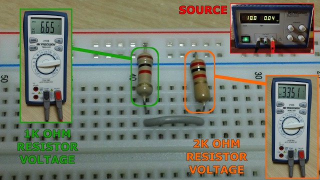
Before you start, take a moment to analyze the image above and perform a quick calculation.
- Source: 10.0V
- Resistors: 1kΩ (Brown-Black-Red) and 2kΩ (Red-Black-Red)
- Calculated voltage across 1kΩ:
- Calculated voltage across 2kΩ:
As you can see, the measured values (3.35V and 6.65V) are very close to the theoretical calculations. Now it's your turn.
Your Task
You will build a voltage divider with the following specifications:
- Input Voltage (): 10V (from your DC power supply)
- Resistor 1 (): 4.7kΩ
- Resistor 2 (): 2.2kΩ
Step 1: Calculate the Theoretical Output
Before you build anything, use the voltage divider equation to calculate the expected across the 2.2kΩ resistor. Record this value.
Step 2: Build the Circuit
Now, construct the circuit on your breadboard. The following video provides an excellent walkthrough of the process. While it uses different resistor values and a Raspberry Pi Pico, the breadboarding technique is identical.
Voltage Dividers for Makers | A Practical Guide
This practical guide from Core Electronics shows you exactly how to assemble the circuit on a breadboard and then test it with a multimeter.
Watch the segment on wiring the circuit. Pay close attention to how the resistors are connected in series between the positive voltage rail and the ground rail. Then, watch the brief clip on using a multimeter to measure the output voltage between the middle point and ground.
Step 3: Measure the Real Output
Set your DC power supply to 10V and power your circuit. Use your multimeter, set to measure DC Voltage, to measure the actual output voltage across your 2.2kΩ resistor. Remember from our last lesson to connect the multimeter probes in parallel with the component you are measuring. Record your measurement.
Step 4: Analyze the Results
Compare your calculated with your measured . Are they identical? Probably not, but they should be very close. Why is there a difference? This question is at the heart of real-world engineering. The following guide will help you explore the reasons.
Modeling Measurement Systems Using Voltage Dividers – PHYS 3330
This lab guide from the University of Colorado Boulder provides a structured way to think about the difference between ideal models and real-world measurements.
Read through the sections on building and testing voltage dividers. Start with the section "Fixed-value voltage divider". This outlines the same calculate-measure-compare process you just did. Next, read the section on higher-value dividers. This part is key. It explains that when circuit resistances become very high, the multimeter's own internal resistance (its input impedance) starts to have a noticeable effect, altering the very circuit it's measuring. This is a perfect example of the "loading effect" we discussed.
To improve your calculation, use your multimeter to measure the actual resistance of your 4.7kΩ and 2.2kΩ resistors before putting them in the circuit. Use these more precise values in your calculation. This will account for resistor tolerance and likely bring your calculated value even closer to your measured one.
4. Application: The Potentiometer
A fixed voltage divider is useful, but what if you need a continuously adjustable output voltage? For this, we use a potentiometer, which is essentially a resistor with a movable "wiper" that taps the voltage at any point along its resistive track. It acts as a variable voltage divider.
Modeling Measurement Systems Using Voltage Dividers – PHYS 3330
Let's return to the CU Boulder lab guide to see how a potentiometer works.
Read the sections titled "Testing the Potentiometer". This explains the internal structure and how to wire it up as a variable voltage source. If you have a potentiometer in your kit, this is an excellent bonus exercise to try.
You'll encounter potentiometers frequently, often as control knobs or as simple sensors whose resistance changes with position.
Conclusion
In this lesson, you bridged the gap between circuit theory and hands-on practice. You successfully performed the fundamental engineering loop of designing, building, and testing a circuit.
Key Takeaways:
- A voltage divider is a simple series-resistor circuit used to scale down a voltage.
- The output is calculated with the formula: .
- The core engineering workflow is Calculate → Build → Measure → Analyze.
- Real-world measurements deviate from ideal calculations due to factors like component tolerance and the loading effect of the measurement instrument (meter input impedance).
- A potentiometer is a variable resistor that can be used to create an adjustable voltage divider.
You now have a practical understanding of a fundamental building block. We noted that resistor tolerance is one reason for measurement discrepancies. In our next lesson, we will focus on interpreting resistor color codes and reading component datasheets, which will give you the tools to know a component's expected value, its tolerance, and other critical parameters before you even place it in a circuit.