Welcome to the fourth lesson of our module on circuit fundamentals. Last time, we developed a powerful technique for analyzing circuits: reducing networks of series and parallel resistors to a single equivalent resistance. This allowed us to apply Ohm's law to the circuit as a whole. However, we also noted its limitation: what happens when a circuit isn't a simple combination of series and parallel elements?
In this lesson, we will equip ourselves with two of the most fundamental laws in circuit analysis: Kirchhoff's Voltage Law (KVL) and Kirchhoff's Current Law (KCL). These laws, based on the conservation of energy and charge, provide a universal framework for analyzing any DC circuit, no matter how complex. Mastering these rules will allow you to move beyond simple reduction and systematically solve for the voltages and currents in any part of a circuit.
Kirchhoff's Current Law (KCL): The Law of Nodes
The first of Kirchhoff's laws is conceptually straightforward and is based on the principle of conservation of charge. Imagine water flowing through a junction of pipes; the total amount of water flowing into the junction must equal the total amount flowing out. Charge in a circuit behaves the same way.
A node is simply a point in a circuit where two or more components connect. Kirchhoff's Current Law states:
The algebraic sum of currents entering any node is zero.
This can also be stated as: the sum of currents flowing into a node must equal the sum of currents flowing out of it. Let's formalize this.
2.13 Kirchhoff's Voltage Law and Kirchhoff's Current Law
This article from the Ultimate Electronics Book provides a clear, foundational explanation of both KCL and KVL. We'll start with the section on KCL.
Read the section titled Kirchhoff's Current Law (KCL). Focus on the two equivalent ways of writing the KCL equation: summing all currents to zero (using signs for 'in' vs. 'out') or setting the sum of incoming currents equal to the sum of outgoing currents. Then, read the following section, "One Too Many Nodes." This is a critical point for practical application: it explains why if you have n nodes in a circuit, you only write n-1 independent KCL equations. This insight is key to setting up solvable systems of equations without redundancy.
As you just read, the core idea of KCL is simple, but its application requires care. You must:
- Assume a direction for each current flowing into or out of a node. It's just a guess for now. If your calculation yields a negative value, it simply means the current actually flows in the opposite direction.
- Be consistent with your sign convention. A common convention is to treat currents entering a node as positive (+) and currents leaving as negative (-).
For example, for a node with currents and flowing in, and flowing out, the KCL equation is:
Or, equivalently:
Kirchhoff's Voltage Law (KVL): The Law of Loops
The second law is based on the conservation of energy. It relates to the voltage changes around any closed path, or loop, in a circuit. Imagine hiking on a mountain trail that starts and ends at the same spot. No matter how many hills you climb (gaining potential energy) or descend (losing potential energy), your net change in elevation when you return to the start must be zero.
Voltage is electrical potential energy per unit charge. KVL applies the same logic to a circuit loop.
The algebraic sum of all voltage rises and drops around any closed loop is zero.
To apply KVL, we must be very careful with our signs. As we "walk" around a loop in a chosen direction (e.g., clockwise), we sum the voltage changes across each component.
For a great in-depth guide on assigning these signs, the following video is extremely helpful.
Kirchhoff's Law, Junction & Loop Rule, Ohm's Law - KCl & KVl Circuit Analysis - Physics
This video by The Organic Chemistry Tutor provides an exceptionally clear breakdown of the sign conventions for KVL, which are often a point of confusion for beginners.
Watch the segment from the discussion of KVL. The instructor explains how to determine whether the voltage across a resistor or a battery should be treated as a positive "lift" or a negative "drop" in your KVL equation, based on your direction of travel around the loop and the assumed direction of current.
To summarize the sign conventions for a KVL loop analysis:
- Voltage Sources:
- Traversing from the negative (-) to the positive (+) terminal is a voltage rise (add ).
- Traversing from the positive (+) to the negative (-) terminal is a voltage drop (add ).
- Resistors:
- First, you must assume a direction for the current flowing through the resistor.
- Traversing the resistor in the same direction as the assumed current is a voltage drop (add ). This is because current naturally flows from higher potential to lower potential.
- Traversing the resistor in the opposite direction to the assumed current is a voltage rise (add ).
The following diagram provides a concise visual summary of these rules.
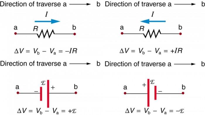
Sign conventions for voltage changes across a resistor (R) and a voltage source (E) when traversing a circuit from point a to point b. The change ΔV is defined as Vb - Va.
With KCL and KVL, we now have a complete toolkit for analyzing any DC circuit.
The General Analysis Procedure
Solving a circuit with Kirchhoff's laws is a systematic process, not unlike writing an algorithm to process data.
- Label Everything: Identify all nodes. Assign a current variable and an assumed direction for every branch of the circuit (e.g., , , ...).
- Apply KCL: Write a KCL equation () for each of the (N-1) independent nodes, where N is the total number of nodes.
- Apply KVL: Choose independent loops that cover all components. Write a KVL equation () for each loop until you have as many unique equations as you have unknown currents.
- Solve the System: You will now have a system of simultaneous linear equations. Use algebra (substitution or elimination) to solve for the unknown currents.
- Calculate Other Values: Once you know the currents, you can use Ohm's Law () to find the voltage drop across any resistor or the power it dissipates ().
Let's see this procedure in action.
KVL and KCL (Circuits for Beginners #11)
In this video, "KVL and KCL," Aaron Danner demonstrates how to combine these laws to solve a circuit problem.
Watch the example starting at this timestamp. Notice how he first applies KCL at a node to relate the currents, then carefully chooses a KVL loop to write a second equation. He also gives a crucial piece of professional advice: avoid drawing KVL loops through an ideal current source, because the voltage across it is unknown and variable.
From Abstraction to Reality
The loops we draw on a schematic correspond to real physical paths for current. The voltages we calculate are real electrical potentials that we can measure with a multimeter.

A circuit demonstrating KVL. According to KVL, the voltage provided by the source (Vs) must equal the sum of the voltage drops across the resistors in the loop. The multimeters here would be measuring VR1 and VR2, and you would find that Vs = VR1 + VR2 (assuming R3 and R4 are not connected). This brings the abstract law into the physical world.
Tying it All Together: The Wheatstone Bridge
Remember the Wheatstone bridge from the end of the last lesson? It's a classic example of a circuit that cannot be simplified using only series and parallel rules. It is, however, a perfect candidate for analysis with Kirchhoff's laws.
Let's consider the general problem presented in this lab manual extract.
[PDF] Physics 252: Introduction to Analog Electronics - Seth Aubin
This document provides a concise overview of Kirchhoff's Laws and poses a classic analysis problem.
First, quickly read the section titled Kirchhoff's Laws for a refresher on the point and loop rules. Next, look at Design Exercise 2-1. This is your challenge: to set up the equations to find the resistance of the bridge. You don't need to solve it fully, but think about the steps: Label the four nodes. Assign five current variables (one for each resistor). Write three KCL equations (for the four nodes). Write two KVL equations (for the upper and lower loops, for instance). You would end up with a system of five equations and five unknowns—a tedious task to solve by hand, but the setup itself is a perfect application of the laws. This is precisely the kind of task that circuit simulation software automates.
- Label the four nodes.
- Assign five current variables (one for each resistor).
- Write three KCL equations (for the four nodes).
- Write two KVL equations (for the upper and lower loops, for instance).
You would end up with a system of five equations and five unknowns—a tedious task to solve by hand, but the setup itself is a perfect application of the laws. This is precisely the kind of task that circuit simulation software automates.
A Note on "Laws": Models and Their Limits
You've expressed a desire to understand things "under the hood," which is the mark of a great engineer. It's important to know that the "laws" we use in engineering are almost always models that work within a certain set of assumptions.
KVL is based on the assumption that the electric field is conservative, meaning a charge looping back to its start point has no net energy change. This holds true for DC circuits. However, as you'll learn later when we discuss AC circuits and electromagnetism, a changing magnetic field can create a non-conservative electric field, inducing a voltage in a loop. This is Faraday's Law of Induction, the principle behind generators and transformers. In such cases, KVL in its simple form () doesn't strictly hold.
For the DC circuits we're analyzing now, KVL is a perfectly valid and essential tool. But it's good to know its boundaries, as this understanding is crucial for dealing with noise, interference, and high-frequency design later on.
Conclusion
In this lesson, you've moved beyond simple circuit reduction and learned a universal method for analysis. Kirchhoff's Laws provide the framework to deconstruct any complex DC circuit into a solvable system of equations.
Key Takeaways:
- Kirchhoff's Current Law (KCL): Based on conservation of charge. The sum of currents entering a node equals the sum of currents leaving it.
- Kirchhoff's Voltage Law (KVL): Based on conservation of energy. The sum of voltage rises and drops around any closed loop must equal zero.
- Sign Conventions are Critical: Methodically applying the correct signs for voltage rises and drops across sources and resistors is essential for a correct analysis.
- Systematic Approach: A combination of KCL, KVL, and Ohm's Law allows you to set up a system of linear equations to solve for any unknown current or voltage in a DC circuit.
We have now covered the three foundational laws of DC circuit analysis: Ohm's Law, KCL, and KVL. In the next lesson, we will bridge the gap between theory and practice by learning how to use a multimeter—the essential tool for any electronics engineer—to measure these theoretical quantities on a real breadboard circuit.