In our last lesson, you built, tested, and analyzed a voltage divider. A key insight from that exercise was that the real-world performance of a circuit doesn't perfectly match the ideal calculations. One of the primary reasons for this discrepancy is component tolerance—the small, allowable deviation from a component's nominal value. This lesson tackles that uncertainty head-on.
To move from building simple circuits to designing robust, reliable systems, you need to know the precise characteristics of the components you're using. Today, we'll focus on the most fundamental of these skills: interpreting the language written on the components themselves. You will learn how to decipher the color bands on through-hole resistors and the cryptic codes on modern Surface-Mount Devices (SMDs). More importantly, you will learn how to go beyond these markings to the definitive source of engineering truth for any component: its datasheet.
By the end of this lesson, you will be able to confidently identify a resistor's value, tolerance, and other key specifications, preparing you for the more complex components we'll encounter soon.
1. Decoding Through-Hole Resistors
The small, cylindrical resistors you've been using on your breadboard are called through-hole or axial-lead resistors. Because they are too small for their values to be printed legibly, the electronics industry long ago standardized a system of color codes.
These colored bands tell you the resistor's nominal resistance value, its tolerance, and sometimes its temperature stability. A great way to get started is by watching a practical demonstration.
How to Read Resistor Color Codes | Electronics Basics
This video from TheElectroBench provides a clear and concise walkthrough of how to read the most common types of resistor color codes.
Watch the following segments to get a solid foundation: Introduction: Understand why color codes are necessary. 4-Band Resistors: Learn the most common format, including how to orient the resistor and read the value and tolerance. Tolerance Explained: This directly connects to our previous lesson, explaining what the tolerance percentage means for the actual resistance range. 5 and 6-Band Resistors: See how more precise resistors add an extra digit and how some include a temperature coefficient band.
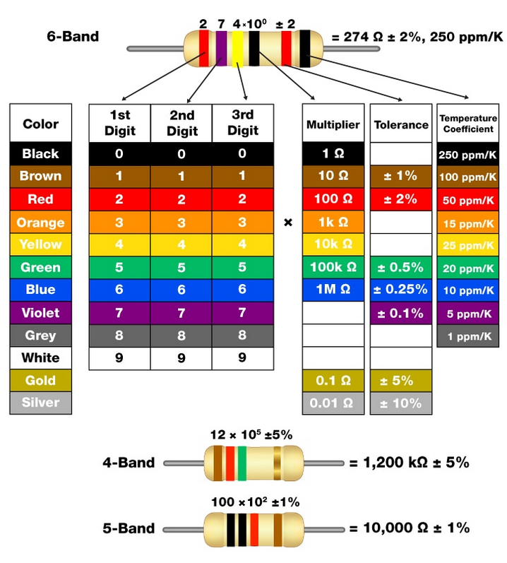
Now that you have seen the process, let's formalize it. The system is based on reading a sequence of bands that represent significant digits, a multiplier (a power of 10), and tolerance. For higher precision resistors, a sixth band for the temperature coefficient is added.
This chart is your decoder key. It's a fundamental reference that engineers often internalize over time.
To solidify your understanding and explore the topic in more detail, let's turn to a comprehensive guide.
How to Read Resistor Color Code: Theory, Practice and Design
This article from Wevolver provides an excellent, in-depth explanation of the color code standard, including how to orient the resistor and examples for each type.
Please read the following sections: Start at "Standard Color Code Values" to see the chart and the crucial rules for reading orientation. Continue through the sections explaining 4-band, 5-band, and 6-band resistors. Focus on the worked examples for each type.
Let's practice. Use the chart above to decode the following resistors:
- 4-Band: Brown, Green, Red, Gold
- 5-Band: Red, Violet, Blue, Orange, Brown
- 6-Band: Yellow, Violet, Black, Brown, Brown, Red
Click to reveal the answers
- Brown (1), Green (5), Red (x10²), Gold (±5%) -> 15 x 100 = 1,500 Ω or 1.5 kΩ ±5%
- Red (2), Violet (7), Blue (6), Orange (x10³), Brown (±1%) -> 276 x 1,000 = 276,000 Ω or 276 kΩ ±1%
- Yellow (4), Violet (7), Black (0), Brown (x10¹), Brown (±1%), Red (50 ppm/K) -> 470 x 10 = 4,700 Ω or 4.7 kΩ ±1%, with a temperature coefficient of 50 ppm/K.
2. Decoding Surface-Mount (SMD) Resistors
While through-hole components are excellent for prototyping, nearly all modern mass-produced electronics use Surface-Mount Devices (SMDs). These components are soldered directly onto the surface of a Printed Circuit Board (PCB), enabling much denser and more automated manufacturing.
Instead of color bands, SMD resistors use a printed alphanumeric code.
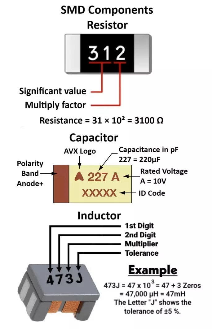
The most common systems for SMD resistors are:
- 3-Digit Code: Two significant digits followed by a multiplier (power of 10). Example:
332= 33 x 10² = 3,300 Ω = 3.3 kΩ. - 4-Digit Code: Three significant digits followed by a multiplier. Used for higher precision (typically 1%) resistors. Example:
4701= 470 x 10¹ = 4,700 Ω = 4.7 kΩ. - EIA-96 (E96) Code: A more complex system for 1% resistors, using a two-digit code to look up the value in a table, followed by a letter for the multiplier.
For a thorough explanation of these coding schemes, the following resource is excellent.
SMD Resistors: Codes, Size, Testing, Tolerance and Selection - Utmel
This guide from Utmel provides a detailed breakdown of the different SMD resistor marking systems. As you're aiming for professional skills, understanding these is essential.
In the article, focus on the section "I. How to Identify SMD Resistor Codes". Read through the explanations and examples for the 3-digit and 4-digit codes, the letter 'R' notation for small values, and finally the E96 system.
3. The Ultimate Source of Truth: The Component Datasheet
The markings on a resistor are just a summary. To design a circuit properly, especially a commercial product, you must consult the component's datasheet. A datasheet is a technical document produced by the manufacturer that provides the complete specifications and characteristics of an electronic component.
Think of it this way: your background in analytics engineering involves understanding the precise schema and constraints of a data source before you build a pipeline. A datasheet serves the same function for a hardware component. It is the definitive documentation.
The markings on a resistor, for instance, don't explicitly state its power rating. A 1/8W resistor and a 1W resistor might both be 10kΩ, but using the wrong one could lead to the component overheating and failing—a classic hardware bug.
Understand resistors better than EVERYONE, a PRO guide to all common resistors.
In this video, James Gatlin highlights a critical limitation of relying only on a resistor's appearance.
Watch the short segment from this timestamp. The key takeaway is that to know a resistor's power capacity (wattage), you must check the manufacturer's datasheet.
Let's look at the key information you will find in a typical resistor datasheet and why it matters.
- Resistance, Tolerance, and Temperature Coefficient: The datasheet will list all available resistance values in a series (like E24 or E96), their corresponding tolerances (e.g., ±1%, ±5%), and their Temperature Coefficient of Resistance (TCR), often in ppm/°C or ppm/K. This tells you how much the resistance will change as the component's temperature changes. The 6th band on a through-hole resistor corresponds to this value.
- Power Rating: Specified in Watts (W), this is the maximum amount of power the resistor can safely dissipate at a given ambient temperature (e.g., 70°C). Exceeding this will destroy the component. The datasheet will also include a "derating curve," which shows you how much the maximum power rating decreases as the ambient temperature rises.
- Maximum Working Voltage: The maximum voltage that can be continuously applied across the resistor.
- Package Dimensions: A detailed mechanical drawing showing the exact physical size, shape, and lead spacing of the component. This is absolutely critical for PCB design, ensuring the "footprint" on your board matches the physical part.
To see how these concepts are applied in component selection, it's worth reviewing the process an engineer follows.
SMD Resistors: Codes, Size, Testing, Tolerance and Selection - Utmel
Let's revisit the Utmel guide. This time, focus on how the specifications we just discussed are used to select the right component.
Read through the section "V. How to Select the Right SMD Resistor". Pay close attention to the subsections on selecting values, choosing tolerance, and selecting the temperature coefficient. Finally, note the last point in the "Procurement Tips" section: "Review Datasheets". This is a non-negotiable rule in professional engineering.
Conclusion
In this lesson, you have learned to translate the markings on passive components into meaningful electrical properties. This is a foundational skill that moves you beyond just following tutorials to truly understanding the materials you are working with.
Key Takeaways:
- Through-hole resistors use a color code to indicate their nominal resistance, tolerance, and sometimes temperature coefficient.
- Surface-mount (SMD) resistors use printed alphanumeric codes (3-digit, 4-digit, or E96) for the same purpose.
- Markings are only a summary. The datasheet is the single source of truth for all of a component's engineering specifications.
- Critical parameters like power rating and precise physical dimensions can only be found in the datasheet, and ignoring them can lead to circuit failure and manufacturing errors.
In our next module, we will begin exploring analog components, starting with diodes. Unlike resistors, whose behavior is relatively simple, diodes and transistors have much more complex characteristics. The habit of consulting a datasheet, which you've started building today, will become even more essential as we analyze these new components.