Hello! In our previous lessons, you've mastered creating VLANs and configuring trunk links to carry their traffic between switches. This was a crucial step in segmenting a network. However, by design, devices in different VLANs still can't communicate with each other. Our goal for this lesson is to bridge that gap.
We will configure what's known as "router-on-a-stick" (ROAS). This is an efficient and common method for using a single physical router interface to route traffic between multiple VLANs. You will learn how to create logical subinterfaces on a router, associate them with your VLANs, and verify that devices on separate VLANs can finally communicate. This is a core skill for your upcoming project.
The "Why" and "How" of Router-on-a-Stick
Before we jump into the commands, it's essential to understand the logic. Since VLANs are separate broadcast domains (like separate LANs), traffic must be sent to a Layer 3 device—a router—to travel between them.
Instead of using a separate physical router port for every single VLAN (which is expensive and doesn't scale), we can use a single physical trunk link between the switch and the router. The router then uses logical subinterfaces to handle the traffic for each VLAN.
The process looks like this:
- A PC in VLAN 10 wants to send data to a PC in VLAN 20.
- The PC sends the traffic to its default gateway (which will be the router).
- The traffic travels over the trunk link from the switch to the router, tagged with VLAN 10.
- The router receives the tagged frame on its physical interface and directs it to the specific subinterface configured for VLAN 10.
- The router looks at its routing table, sees the destination is on the network connected to its VLAN 20 subinterface, and routes the packet internally.
- The router then sends the packet back out the same physical interface, but this time tagged for VLAN 20.
- The switch receives the frame tagged for VLAN 20 and forwards it to the destination PC.
The following video provides a great visual explanation of this concept and the overall topology.
How to Configure Router on a Stick in 10 MINUTES | CCNA Basics
This video from Paolo Reyes provides a clear and concise explanation of the router-on-a-stick concept and why it's necessary for inter-VLAN communication.
Please watch the first part of the video, from the beginning to the explanation. Pay close attention to the traffic flow diagram showing how a ping gets from one VLAN to another via the router.
Configuration Steps
Configuring router-on-a-stick involves three main parts: the switch, the router, and the end-user devices (PCs).
1. Switch Configuration (The Trunk Port)
This part should be familiar from our previous lessons. The switch port that connects to the router must be configured as a static trunk port to carry traffic for all the necessary VLANs.
Switch(config)# interface GigabitEthernet0/1
Switch(config-if)# description Link to Router
Switch(config-if)# switchport mode trunk
2. Router Configuration (The Subinterfaces)
This is the core of the ROAS configuration. We will take a single physical interface on the router and create multiple virtual subinterfaces on it. Each subinterface will be configured as the default gateway for one VLAN.
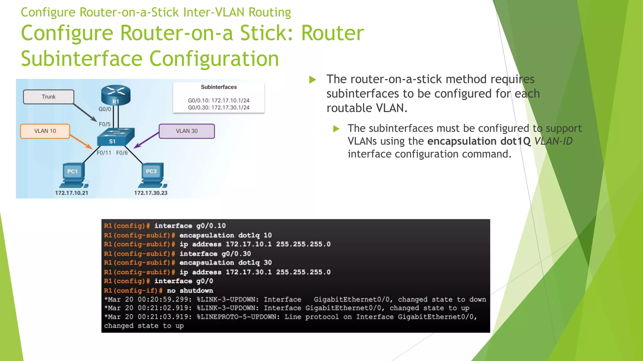
The configuration process for each subinterface follows two key commands:
encapsulation dot1q <vlan_id>: This command tells the subinterface which VLAN ID it is responsible for. It enables the subinterface to understand the 802.1Q tags coming from the switch.ip address <ip_address> <subnet_mask>: This assigns an IP address to the subinterface, which will serve as the default gateway for all devices in that VLAN.
The following guide provides a formal, step-by-step breakdown of the router configuration.
Router-on-a-Stick Inter-VLAN Routing (4.2)
This article from Cisco Press is an authoritative guide on router-on-a-stick. This section details the precise commands for creating and configuring subinterfaces on a Cisco router.
Read the section titled "R1 Subinterface Configuration (4.2.4)". Pay special attention to the explanation of the interface <id>.<subinterface_id> syntax, the encapsulation dot1q command, and the final step of enabling the physical interface with no shutdown.
Now, let's see these commands in a practical demonstration. The following video walks through the entire configuration, from the switch to the router.
How to Configure Router on a Stick in 10 MINUTES | CCNA Basics
This video continues the demonstration by configuring both the switch and the router for a complete router-on-a-stick setup.
Watch from the switch config to see the trunk port being set up. Then, watch the crucial router configuration from the router config, where subinterfaces are created, encapsulation is set, and IP addresses are assigned.
3. Host Configuration (The Default Gateway)
This final configuration step is simple but absolutely critical. For a host to send traffic outside its local subnet (i.e., to another VLAN), it must know where to send it. You must configure each host's default gateway to be the IP address of the router subinterface corresponding to its VLAN.
- A PC in VLAN 10 (e.g., 192.168.10.100) must have its default gateway set to the IP address of the router's VLAN 10 subinterface (e.g., 192.168.10.1).
- A PC in VLAN 20 (e.g., 192.168.20.50) must have its default gateway set to the IP address of the router's VLAN 20 subinterface (e.g., 192.168.20.1).
Verifying Inter-VLAN Routing
After configuration, you must verify that everything is working as expected. Verification happens at multiple levels.
Verification from the Hosts
The ultimate test is a ping from a host in one VLAN to a host in another. A successful ping proves that the entire path—from the source PC, across the trunk to the router, through the router's routing logic, and back across the trunk to the destination PC—is working correctly.
Verification on the Router
On the router, two commands are essential for verifying a ROAS configuration:
show ip interface brief: This command quickly shows you if your subinterfaces are "up" and "up" and have the correct IP addresses.show ip route: This is the most important command. It displays the router's routing table. For a working ROAS setup, you should see "directly connected" routes (marked with a 'C') for each of the subnets you configured on your subinterfaces.
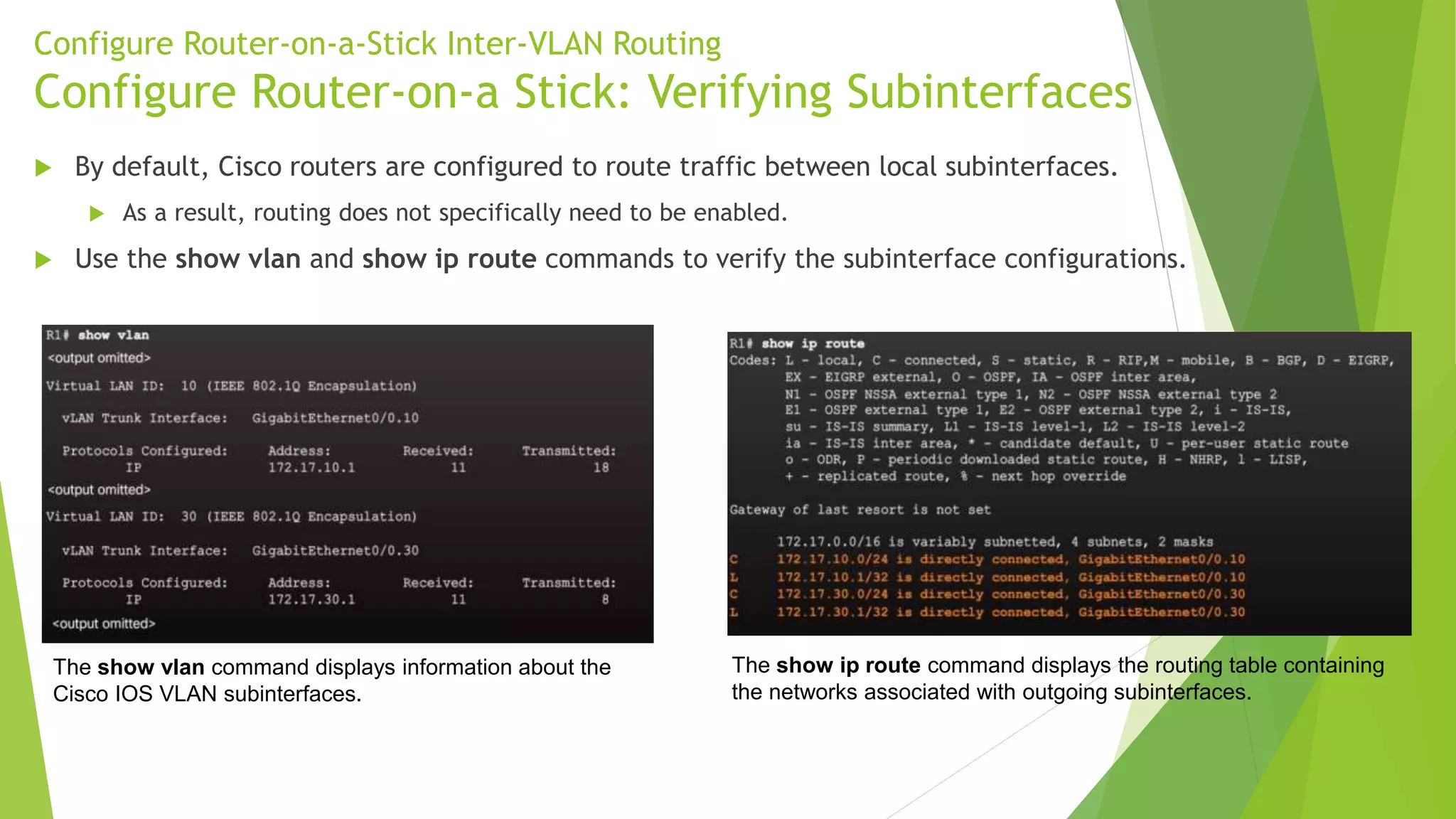
The Cisco Press article you reviewed earlier also has an excellent section on verification. It's worth reviewing their examples.
Router-on-a-Stick Inter-VLAN Routing (4.2)
This section provides clear examples of the show commands used to verify and troubleshoot the router-on-a-stick configuration.
Focus on the subsections for show ip route and show ip interface brief. Compare the command outputs in the examples to the configuration that was applied. This reinforces the link between what you configure and how you verify it.
Practical Exercise
Let's apply these concepts. Consider the following network requirement:
- You have a switch connected to a router
R1via interfaceGigabitEthernet0/0. - You need to provide inter-VLAN routing for two user groups:
- VLAN 100 (FINANCE): IP Network
10.10.100.0/24 - VLAN 200 (DEV): IP Network
10.10.200.0/24
- VLAN 100 (FINANCE): IP Network
- The router should use the first available IP address in each subnet as its subinterface address (e.g.,
.1).
Your Tasks:
- Write down the full sequence of commands required to configure the subinterfaces on router
R1. - A user's computer in the DEV group has the IP address
10.10.200.55. What IP address must be configured as its default gateway? - What command would you run on
R1to confirm that it has learned the routes for both the FINANCE and DEV networks?
Solution
-
Router R1 Configuration:
R1# configure terminal R1(config)# interface GigabitEthernet0/0 R1(config-if)# no shutdown R1(config-if)# exit R1(config)# interface GigabitEthernet0/0.100 R1(config-subif)# description Gateway for FINANCE VLAN R1(config-subif)# encapsulation dot1q 100 R1(config-subif)# ip address 10.10.100.1 255.255.255.0 R1(config-subif)# exit R1(config)# interface GigabitEthernet0/0.200 R1(config-subif)# description Gateway for DEV VLAN R1(config-subif)# encapsulation dot1q 200 R1(config-subif)# ip address 10.10.200.1 255.255.255.0 R1(config-subif)# end -
Default Gateway: The computer with IP
10.10.200.55must have its default gateway set to10.10.200.1. -
Verification Command: To confirm the routes, you would run
show ip routeonR1. You should expect to see two "directly connected" entries, one for the10.10.100.0/24network and one for the10.10.200.0/24network.
Conclusion
You have now learned how to break down the barriers between VLANs using the router-on-a-stick method. This powerful technique is a fundamental building block in modern network design and will be directly applicable to your project.
Key Takeaways:
- Router-on-a-stick uses a single trunk link and router subinterfaces to enable inter-VLAN routing.
- The switch port connected to the router must be configured as a trunk.
- On the router, each subinterface requires
encapsulation dot1q <vlan-id>and a unique IP address. - The IP address of a subinterface serves as the default gateway for all hosts within that VLAN.
- Verification is done with
pingfrom hosts andshow ip routeon the router.
In our next lesson, we will dive into the essential troubleshooting tools every network engineer uses daily: ping and traceroute. Now that you know how to build a multi-VLAN network, you will learn how to systematically test connectivity and pinpoint the exact location of a failure.