Hello! In our last lesson, we established a systematic methodology for troubleshooting network issues. We saw how tools like traceroute can reveal the path a packet takes through a network, hop by hop. That naturally leads to our topic for today: how does each router in that path decide where to send the packet next?
This lesson kicks off our module on IP Routing Fundamentals. We will explore the core logic that underpins all IP networking. Your goal for this lesson is to understand how a router uses its IP routing table to make forwarding decisions. This is a foundational concept that will be critical for configuring and troubleshooting the multi-router topology in your project.
1. The Core Function of a Router
At its heart, a router is a device that connects different networks. Its primary job is to receive an IP packet on one interface and forward it out of another interface, bringing it one step closer to its final destination. This process is often called packet switching.
Let's break down the three main steps a router takes when it receives a packet destined for another network.
Routing Decisions (1.2) > Routing Concepts
This excerpt from an article by Cisco Press clearly outlines the fundamental steps a router performs to forward a packet.
Read the section titled "Router Switching Function (1.2.1.1)". Focus on the three major steps listed and illustrated in the first figure: De-encapsulation: The router strips off the Layer 2 (e.g., Ethernet) frame to expose the Layer 3 IP packet inside. Examination: It looks at the destination IP address within the packet. Re-encapsulation: It wraps the IP packet in a new Layer 2 frame, appropriate for the outgoing interface, and sends it on its way. Notice the key takeaway: while the Layer 2 source and destination MAC addresses change at every hop, the Layer 3 source and destination IP addresses remain unchanged for the entire journey.
This decision-making process can be visualized as a flowchart. The router asks a series of questions to determine the packet's fate.
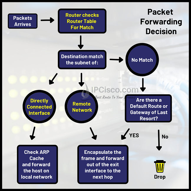
2. The IP Routing Table: A Router's Road Map
To make these forwarding decisions, a router needs a "road map." This map is the IP routing table, a data structure stored in the router's memory that lists all the networks the router knows how to reach.
The following image breaks down the key fields in a typical routing table entry on a Cisco device.

For our purposes today, the most important fields are:
- Destination Network/Prefix: The network address and subnet mask (e.g.,
192.168.3.0/24). - Next-Hop Address: The IP address of the next router to send the packet to.
- Outgoing Interface: The physical or logical interface the router will use to send the packet.
The simplest routes are those for networks the router is physically connected to. Let's see how these appear in the routing table.
Free CCNA | Routing Fundamentals | Day 11 (part 1) | CCNA 200-301 Complete Course
This video from Jeremy's IT Lab provides a fantastic introduction to the show ip route command and explains the two most fundamental types of routes.
Watch the segment from Connected and Local routes. As you watch, focus on: The difference between a Connected (C) route, which represents the entire network a router's interface is on, and a Local (L) route, which represents the specific IP address of the router's own interface. How these routes are automatically added to the routing table when you configure an IP address on an interface and enable it.
3. The Forwarding Decision: Longest Prefix Match
A router's routing table can have multiple entries. What happens if a packet's destination IP address matches more than one route? For example, a packet destined for 192.168.2.82 would match a route for 192.168.2.0/24 AND a route for 192.168.2.80/29.
To resolve this, routers use a simple but powerful rule: the longest prefix match. The router will always choose the route with the most specific network mask (the longest prefix).
- A
/29prefix is more specific than a/24prefix. - A
/27prefix is more specific than a/8prefix.
The next video segment explains this rule with clear examples.
Free CCNA | Routing Fundamentals | Day 11 (part 1) | CCNA 200-301 Complete Course
Continuing with the same video, we now get to the core of the router's decision logic.
First, watch the explanation of the most specific match. This section explains why the /32 Local route is chosen over the /24 Connected route for packets addressed to the router itself. Then, watch the practical examples. Pay close attention to the last example, which shows what happens when a packet arrives for a destination that has no matching route in the table: the router drops it.
To truly understand how this works, it's helpful to visualize the process in binary, as this is what the router is actually doing—comparing bits.
This article from NetworkLessons.com provides a more in-depth look at the longest prefix match rule, including binary examples.
Read the "Explanation" and "Binary Example 1" sections. Don't worry about the Administrative Distance and Metric for now; we'll cover those in a future lesson. Focus on how the destination IP address is compared bit-by-bit against the prefixes in the routing table to find the one with the longest match.
This process is what allows you to create more specific routes to "carve out" exceptions from broader, more general routes.
4. Following a Packet's Journey
Let's now tie all these concepts together and follow a packet from a source PC to a destination PC across several routers. Each router along the path will perform the same process: receive the frame, de-encapsulate it, look up the destination IP in its routing table using the longest prefix match rule, re-encapsulate the packet in a new frame, and forward it to the next hop.
Free CCNA | The Life of a Packet | Day 12 | CCNA 200-301 Complete Course
This video, also from Jeremy's IT Lab, gives a complete "Life of a Packet" walkthrough. It perfectly illustrates the concepts we've discussed.
Watch the following two segments: First Hop: From PC1 to R1. This shows the initial routing lookup. PC1 sends the packet to its default gateway, R1. R1 receives it, checks its routing table for the final destination (192.168.4.0/24), and determines the next hop is R2 (192.168.12.2). Summary: Watch the short summary at the end. This reinforces the crucial point that the Layer 3 IP packet remains unchanged, while the Layer 2 frame is rebuilt at each hop.
As you build and troubleshoot your project network, you can use the command show ip route <destination_ip> on a router to see exactly which route it would choose to forward a packet to that specific destination.
Conclusion
In this lesson, you've learned the fundamental logic behind how every router operates. This process is the foundation upon which all internet communication is built.
Key Takeaways:
- A router's main job is to forward packets between networks. It does this by de-encapsulating, examining the destination IP, and re-encapsulating the packet.
- The IP routing table is the router's map, containing entries for all known networks.
- When multiple routes match a destination, the router uses the longest prefix match rule, selecting the most specific route (the one with the longest subnet mask).
- If no route in the table matches the destination, and there is no "default route" configured, the packet is discarded.
In our next lesson, we will explore how a router builds its routing table. We will differentiate between the three main types of routes: directly connected, static, and dynamic. This will move us from understanding how the table is used to how it is populated.