Hello! Welcome back to our journey through the Data Link Layer.
In our last lesson, we got our hands dirty with the command line, using ipconfig and ifconfig to find your computer's MAC addresses. We established that these are unique hardware identifiers used for communication within a local network.
Today, we're going to answer the next logical question: how are these MAC addresses actually used to send data? The answer lies in a fundamental concept of local networking: the Ethernet frame. This lesson directly addresses the learning outcome: Describe the structure of an Ethernet frame. We'll dissect this data "container" piece by piece to understand how your computer packages data for its first hop across the network.
From Data to Frame: The Need for Structure
Imagine you have a piece of data—say, the first part of a file you're downloading. To send it to another computer on your local network (e.g., from your laptop to your printer), you can't just send the raw stream of bits. The receiving device wouldn't know where the data begins or ends, who it's from, who it's for, or if it arrived without errors.
To solve this, networking protocols wrap data in a structured container called a frame. You can think of a frame as a digital envelope. Just like a physical envelope has specific places for the recipient's address, the sender's address, and a stamp, an Ethernet frame has a standardized format with fields for all the necessary information.
This process is a key part of what we call encapsulation, which we briefly touched on when discussing layered models. At the Data Link Layer (Layer 2), data from the layer above (the Network Layer) is encapsulated into an Ethernet frame for local delivery.
The CBT Nuggets article below offers a great analogy for this, comparing an Ethernet frame to a postcard.
What is the Ethernet Frame Format? - CBT Nuggets
To start, let's read a brief introduction from the article 'What is the Ethernet Frame Format?'. This will help solidify the concept of a frame using a simple analogy.
Please read from the beginning of the article down to just before the 'What are the Components of an Ethernet Frame?' section. Focus on the postcard analogy and the high-level purpose of the frame.
The Anatomy of an Ethernet Frame
Now, let's open up that digital envelope and examine its parts. A standard Ethernet II frame (the most common type used today) has a very specific structure. Given your background in computer science, you can think of it as being conceptually similar to a C struct: a collection of named fields, each with a defined size and purpose, all bundled together into a single unit.
Here is a visual breakdown of a standard frame:
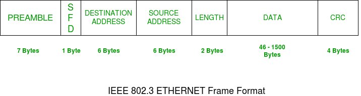
Let's walk through each of these fields one by one.
1. Preamble (7 Bytes) & Start Frame Delimiter (SFD) (1 Byte)
Before the actual frame is sent, the sending Network Interface Card (NIC) transmits an 8-byte sequence.
- Preamble: A sequence of 7 bytes consisting of alternating 1s and 0s (
10101010...). This acts like a "wake-up call" for the receiving NIC, allowing its internal clock to synchronize with the sender's clock. This ensures the receiver can correctly interpret the timing of the incoming bits. - SFD: The final byte is
10101011. The final11breaks the alternating pattern and signals, "The preamble is over. The actual frame starts with the very next bit!"
Technically, the Preamble and SFD are part of the Physical Layer (Layer 1) transmission, but they are essential for the Data Link Layer (Layer 2) frame to be received correctly.
2. Destination MAC Address (6 Bytes)
This is the first field of the actual frame. It contains the 48-bit MAC address of the device the frame is intended for. This is the "To:" field on our digital envelope. When a switch receives this frame, it will look at this address to decide where to forward it.
3. Source MAC Address (6 Bytes)
This 6-byte field contains the 48-bit MAC address of the device that sent the frame. This is the "From:" field. It allows the recipient to know who the data came from and to send a reply if necessary. This is the address you found using ipconfig or ifconfig in the last lesson.
4. EtherType / Length (2 Bytes)
This 2-byte field is clever and has a dual purpose, though one use is far more common today.
- Length: In very old Ethernet standards, this field indicated the length of the payload. If the value is 1500 or less, it's interpreted as the length.
- EtherType: In the modern Ethernet II standard, if the value is 1536 (or
0x0600in hex) or greater, it's an EtherType field. This is its primary use today.
The EtherType tells the receiving computer's operating system what kind of data is in the payload. It identifies the protocol of the encapsulated data from the layer above (Layer 3). Common EtherType values include:
0x0800: The payload contains an IPv4 packet.0x0806: The payload contains an ARP packet. (We'll cover ARP soon!)0x86DD: The payload contains an IPv6 packet.
This field is the critical link that allows the Data Link Layer to hand off the payload to the correct protocol handler at the Network Layer.
5. Payload (Data) (46 to 1500 Bytes)
This is the actual data being transported—the "contents" of the envelope. It's the data packet passed down from the Network Layer (e.g., an IP packet).
- Minimum Size (46 bytes): Ethernet frames must have a minimum total size to be valid. If the data from the upper layer is less than 46 bytes, padding is added to meet this minimum.
- Maximum Size (1500 bytes): This is the standard Maximum Transmission Unit (MTU). If a Network Layer packet is larger than 1500 bytes, it must be fragmented into smaller pieces before being placed in Ethernet frames.
6. Frame Check Sequence (FCS) (4 Bytes)
This is a 4-byte field at the very end of the frame used for error detection.
- The sending device performs a calculation called a Cyclic Redundancy Check (CRC) on all the fields of the frame (from the Destination MAC to the end of the Payload).
- It places the result of this calculation in the FCS field.
- The receiving device performs the exact same CRC calculation on the frame it receives.
- It then compares its calculated result with the value in the FCS field.
- If they match, the frame is considered error-free and is processed.
- If they do not match, the frame is assumed to have been corrupted during transmission and is silently discarded.
It's important to note that Ethernet provides error detection, but not error recovery. It doesn't ask the sender to retransmit a corrupt frame; that responsibility is left to higher-layer protocols like TCP.
Visualizing the Frame
To see these components explained in a dynamic way, let's watch a video that walks through the frame format.
Frame formats | Networking tutorial (6 of 13)
This video from Ben Eater provides a very clear, step-by-step explanation of the Ethernet frame format. It builds on the concepts we've just discussed.
Please watch from the section explaining the Ethernet frame format (timestamp 02:06) until the end of the discussion on the Frame Check Sequence (timestamp 06:46). Pay attention to how he explains the purpose of each field.
For a slightly different perspective that also details common EtherType values, this next video is also very helpful.
The Data Link Layer, MAC Addressing, and the Ethernet Frame
The video 'The Data Link Layer, MAC Addressing, and the Ethernet Frame' gives another excellent overview, with a particular focus on the EtherType field and the Frame Check Sequence.
Watch from timestamp 08:28 to 15:24. This will reinforce what you learned from the Ben Eater video and provide additional details, especially about the different protocol numbers used in the EtherType field.
Finally, the Wikipedia page for the "Ethernet frame" is an excellent, definitive reference. The table under the "Structure" section provides a dense, accurate summary.
For a detailed technical reference, the Wikipedia article on Ethernet frames is invaluable. We'll focus on the main structure table and the descriptions of each component.
Review the table in the 'Structure' section to see all the fields laid out. Then, read the subsections under 'Frame – data link layer' that describe the 'Header', 'Payload', and 'Frame check sequence'. This will provide a formal definition for the concepts we've covered.
Conclusion
You've now dissected the fundamental building block of local area networks. By understanding the structure of an Ethernet frame, you can see exactly how the MAC addresses you found in the last lesson are put to use, and how data from the internet at large (as an IP packet) gets packaged for its final journey across your local network.
Key Takeaways:
- An Ethernet frame is a standardized data structure used to transport data across a local network at Layer 2.
- The frame begins with a Preamble and SFD for clock synchronization.
- The header contains the Destination and Source MAC addresses, which are used for local addressing.
- The EtherType field is crucial, as it identifies the type of data in the payload (e.g., IPv4, ARP).
- The Payload carries the actual data from the layer above, typically an IP packet.
- The Frame Check Sequence (FCS) provides error detection using a CRC, but does not provide error correction.
Preview of the Next Lesson:
Now that we know what a frame is and what information it contains, we'll explore how network devices use it. In the next lesson, we will learn how a network switch forwards frames using a MAC address table. You'll see how this simple, yet powerful, device reads the destination MAC address in each frame to intelligently deliver data only where it needs to go, making our local networks efficient.