Introduction
Welcome to the next lesson in our exploration of the 4G LTE architecture. In the previous lesson, we walked through the entire LTE attach procedure, observing the complex sequence of messages that allows a phone to connect to the network. You saw messages like RRC Connection Setup, NAS Attach Request, and RRC Connection Reconfiguration flying back and forth between the UE, eNodeB, and the core network.
Today, we'll zoom in on the two most important signaling protocols that make this procedure happen: Radio Resource Control (RRC) and Non-Access Stratum (NAS). Our goal is to explain their distinct roles in managing the UE's connection to the network and its data sessions. Understanding this separation is fundamental to understanding LTE security, as it clarifies which part of the network is responsible for which function.
Think of it this way: RRC is like setting up a secure, dedicated phone line from your house to the local telephone exchange. NAS is the actual conversation you have over that line with the central office operator to get authorized and connected to the wider world.
The Two Strata: Access vs. Non-Access
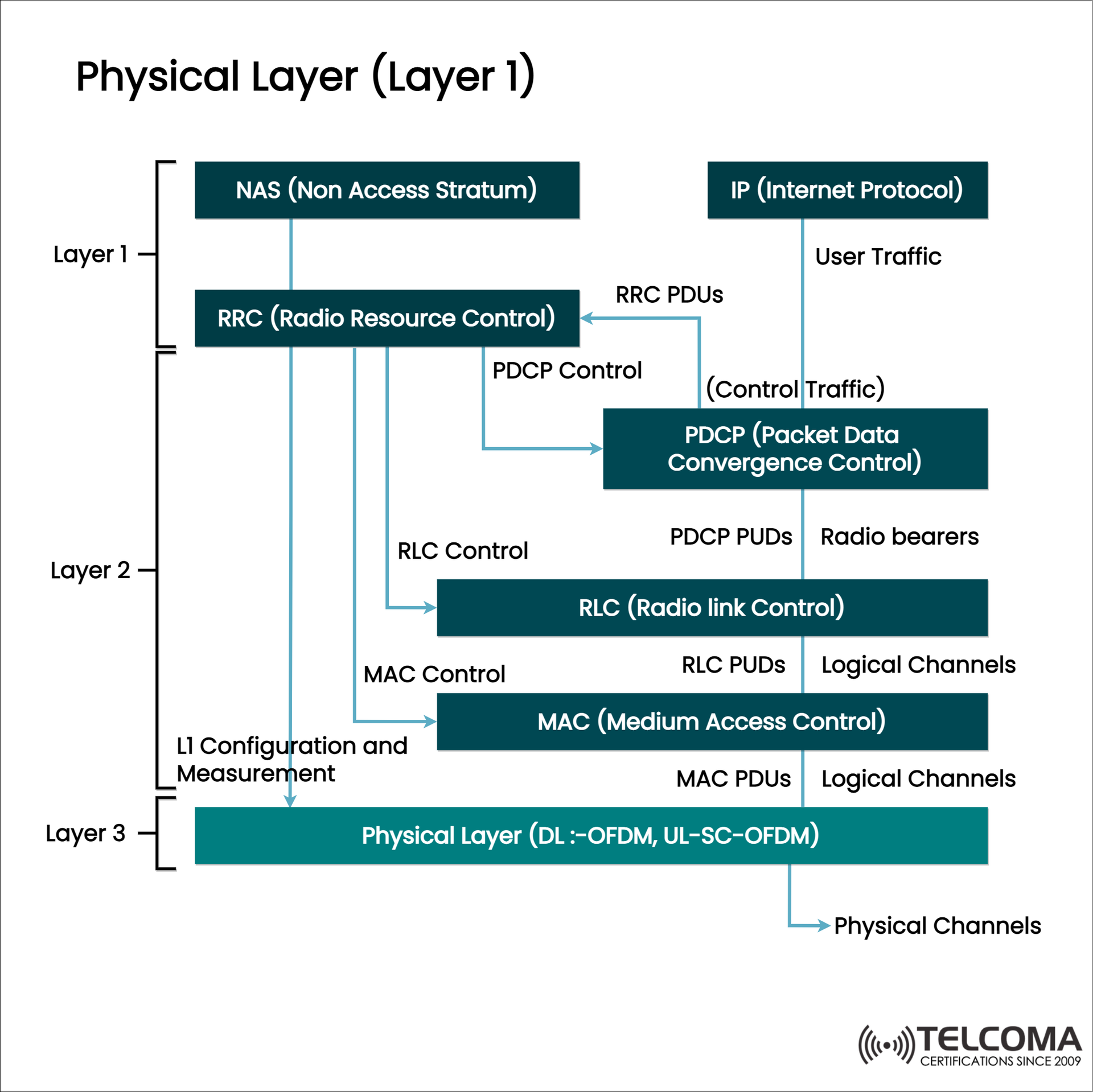
To understand RRC and NAS, we first need to understand how the LTE protocol stack is organized. Similar to the OSI model you're familiar with from IP networking, cellular protocols are arranged in layers. In LTE, these layers are broadly grouped into two "strata."
-
Access Stratum (AS): This stratum includes all protocols related to the radio access network—the "air interface." The communication here is primarily between your User Equipment (UE) and the cell tower (eNodeB). The main signaling protocol of the Access Stratum is Radio Resource Control (RRC). Its job is to manage the state and configuration of the radio link.
-
Non-Access Stratum (NAS): This stratum contains protocols for communication between the UE and the core network, specifically the Mobility Management Entity (MME). These protocols are "non-access" because they are designed to be independent of the specific radio technology used. The same NAS procedures could, in theory, run over Wi-Fi or another type of access. NAS is responsible for user identity, authentication, and managing data sessions.
The following video provides a concise explanation of this fundamental division.
LTE Attach Part 4 (final): AS & NAS; EMM and ESM
This clip from the video 'LTE Attach Part 4 (final): AS & NAS; EMM and ESM' by Irfan Ali clearly defines the Access Stratum and Non-Access Stratum.
Watch the segment from 00:00 to 02:24 to understand the core difference between AS and NAS. Then, watch from 17:09 to 18:22, which shows the control plane protocol stack and how RRC and NAS fit together.
RRC: The Radio Connection Manager
The Radio Resource Control (RRC) protocol is the master controller of the radio interface. It lives in the Access Stratum and its sole purpose is to manage the radio resources between the UE and the eNodeB.
Key responsibilities of RRC include:
- Broadcasting System Information: The eNodeB uses RRC to broadcast essential information that UEs need to connect to the cell, such as the network's identity (PLMN-ID) and configurations for accessing the channel.
- Connection Management: RRC establishes, maintains, and releases the signaling connection between the UE and eNodeB. This is the
RRC Connection Request/Setup/Releasemessage exchange you saw in the attach procedure. - Bearer Management: It sets up, modifies, and tears down the "radio bearers" – the logical channels over the air that carry both signaling (
Signalling Radio Bearersor SRBs) and user data (Data Radio Bearersor DRBs). - Security: RRC manages the configuration of encryption and integrity protection for all data crossing the air interface (this is called AS security).
- Mobility: It handles procedures like cell handovers, where a UE is seamlessly moved from one eNodeB to another.
- Transport for NAS: Crucially, RRC provides a container service to transport NAS messages transparently between the UE and the eNodeB. The eNodeB simply forwards these messages on to the MME without interpreting them.
The excellent ShareTechnote resource provides a detailed list of messages in the attach flow. Notice how many messages start with "RRC" – these are all commands for managing the radio link.
LTE : Basic Call Flow - 4G | ShareTechnote
Let's look at the 'LTE : Basic Call Flow' page from ShareTechnote, a definitive resource for cellular engineers. We'll focus on the RRC-specific steps.
Skim the sections titled 'RRC : RRC Connection Request', 'RRC : RRC Connection Setup', and 'RRC : Security Mode Command'. You don't need to understand every parameter, but notice that these messages are configuring radio-specific details like bearers (SRBs) and security algorithms for the air interface.
NAS: The Mobility and Session Manager
While RRC manages the radio link, the Non-Access Stratum (NAS) protocols handle the UE's relationship with the core network. This is a direct, logical conversation between the UE and the MME. The eNodeB acts only as a mail carrier, passing NAS messages back and forth.
NAS signaling is split into two key functions, each with its own protocol:
- EPS Mobility Management (EMM): This protocol manages the UE's overall status and mobility from the core network's perspective. Think of it as managing your "login status" with the network.
- Procedures: Attach, Detach, Authentication, NAS Security Setup, and Tracking Area Updates (TAU). A TAU is how a UE in idle mode periodically reports its general location to the network.
- EPS Session Management (ESM): This protocol is responsible for managing the user's data connectivity sessions, known as EPS Bearers.
- Procedures: Activating, modifying, and deactivating bearers. This is where a UE requests a PDN connection (e.g., to the internet), gets an IP address, and establishes a pipe for its data traffic.

Let's dive deeper into EMM and ESM with another segment from the Irfan Ali video.
LTE Attach Part 4 (final): AS & NAS; EMM and ESM
This part of the video explains the EMM and ESM sublayers of NAS, clarifying their distinct responsibilities for mobility and data sessions.
Watch from 02:24 to 12:55. This section covers EMM states and procedures, ESM states and procedures, and how the two protocols are related but distinct. Pay close attention to the concept of 'always-on IP connectivity' and how EMM and ESM are coupled.
How RRC and NAS Work Together
The key to understanding the system is to see how these two protocols collaborate.
- A UE needs to send a NAS message to the MME (e.g.,
Attach Request). - To do this, it first uses RRC to establish an
RRC Connectionwith the local eNodeB. This sets up a Signalling Radio Bearer (SRB). - The UE then places its
NAS Attach Requestmessage inside anRRC Connection Setup Completemessage. - The eNodeB receives the RRC message, extracts the NAS message from it, and forwards the NAS message to the MME via the S1-AP protocol.
- The MME processes the NAS message. When it needs to reply (e.g., with a
NAS Attach Accept), it sends the NAS message to the eNodeB. - The eNodeB encapsulates the
NAS Attach Acceptmessage inside anRRC Connection Reconfigurationmessage and sends it to the UE over the radio.
This process of carrying one protocol's message inside another's is a form of tunneling, a concept you're likely familiar with from VPNs and IP-in-IP. Here, RRC is the transport for NAS over the air.
The Wireshark analysis video we looked at in the last lesson perfectly illustrates this.
LTE Call Flow - Wireshark (Pcap) analysis of LTE UE Attach
Let's revisit a clip from the 'LTE Call Flow - Wireshark (Pcap) analysis' video by Telco Bytes. It shows exactly how a NAS message is embedded within a larger message destined for the eNodeB.
Watch from 20:38 to 23:54. The speaker explains the S1-AP: Initial Context Setup Request message from the MME to the eNodeB. Notice how inside this message, there are transparent containers for both RRC configuration and the NAS Attach Accept message, which are to be forwarded to the UE.
Conclusion
In this lesson, we dissected the roles of the two primary signaling protocols in LTE. Understanding their separation is crucial for analyzing network behavior and security.
Key Takeaways:
- RRC (Radio Resource Control): Belongs to the Access Stratum (AS). It is the radio connection manager, handling communication between the UE and eNodeB. It sets up, maintains, and releases the radio link and bearers.
- NAS (Non-Access Stratum): It is the mobility and session manager, handling communication between the UE and MME. It is independent of the radio technology.
- EMM vs. ESM: NAS is divided into EPS Mobility Management (EMM) for user authentication and mobility, and EPS Session Management (ESM) for creating and managing data bearers and IP connectivity.
- RRC as a Transport: NAS messages are encapsulated within RRC messages to be transported over the air interface. The eNodeB acts as a simple forwarder for this NAS traffic.
Preview of the Next Lesson:
We've now established that the goal of the ESM sublayer within NAS is to manage "EPS Bearers." But what exactly is a bearer? In our next lesson, we will explain the function of bearers and GTP tunneling in transporting user data. You'll learn how these logical "pipes" are constructed through the core network to carry your IP packets from your phone to the internet and back.