Introduction
In our last lesson, you learned to identify the key components of the 4G Evolved Packet Core (EPC): the MME, SGW, PGW, and HSS. You now know what these core network "servers" are and their high-level functions.
Today, we will connect the dots. This lesson will walk you through the LTE attach procedure, which is the sequence of messages that allows your phone (UE) to connect to the network, get authenticated, and establish a data connection. This process is the foundation for all communication in an LTE network, and understanding its steps is crucial for identifying potential security weaknesses.
Our goal is to describe the entire flow, from the initial radio handshake to the moment your phone has a live IP connection. We'll break this down into three main phases:
- Initial Access: Establishing a basic signaling connection over the radio interface.
- Authentication and Security: Verifying your identity and encrypting the connection.
- Bearer Setup: Creating the data "pipe" through the core network to the internet.
This procedure involves a complex dialogue between the UE, eNodeB, and all the EPC components you learned about previously.
A Map of the Attach Procedure
Before diving into the details, it's helpful to have a high-level map of the process. The following diagram shows all the network entities and the general flow of messages required to get a UE connected. Think of this as our itinerary for this lesson.
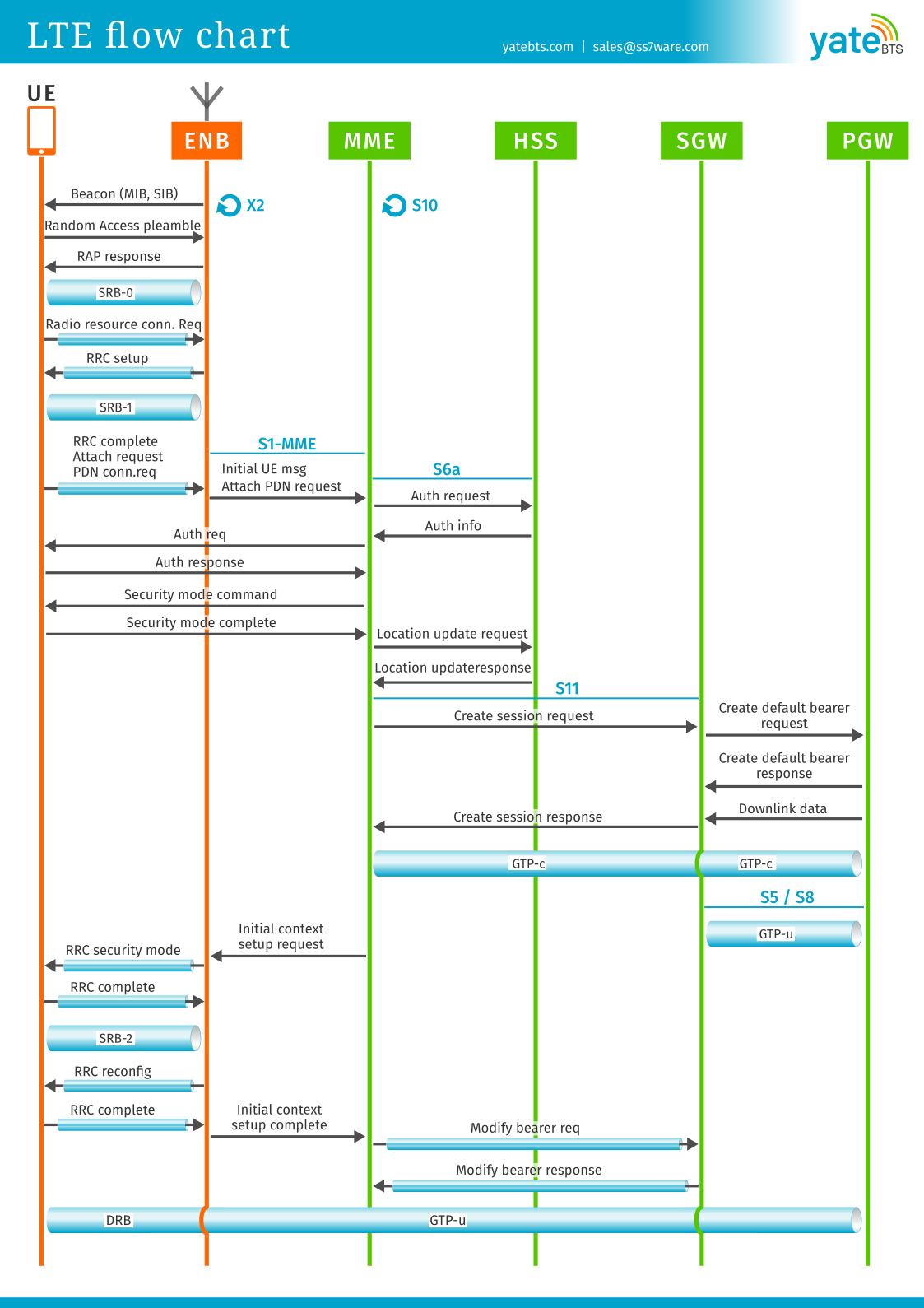
As you can see, the attach procedure is a collaborative effort. The eNodeB manages the radio link, the MME orchestrates the overall process, the HSS validates your identity, and the SGW and PGW build the tunnel for your data.
The Step-by-Step Call Flow
Let's now walk through the procedure step-by-step. The following video provides an excellent and clear explanation of the entire message flow. We will watch it in segments corresponding to the main phases of the attach.
LTE Attach Part 3: Attach Call Flow
The video 'LTE Attach Part 3: Attach Call Flow' by Irfan Ali provides a fantastic walkthrough of the attach procedure. We'll start with the first phase: getting a connection to the eNodeB.
Watch the video from 01:07 to 06:30. This segment covers the Random Access procedure and the initial Radio Resource Control (RRC) connection setup.
Phase 1: Initial Access and RRC Connection Setup
As the video explained, the first step isn't to talk to the core network, but to establish a dedicated signaling channel with the local cell tower (eNodeB). This is analogous to getting a specific frequency to talk on before you can pass on a more complex message.
This initial handshake consists of a few key messages:
- Random Access Preamble: The UE sends a short, generic signal to the eNodeB to get its attention.
- Random Access Response: The eNodeB responds, providing initial timing alignment and a temporary identifier called the Cell Radio Network Temporary Identity (C-RNTI). This C-RNTI will be used to identify the UE on the radio channel for the next steps.
- RRC Connection Request: Now using its dedicated slot, the UE sends a formal request to establish a signaling connection.
- RRC Connection Setup: The eNodeB accepts the request and provides the UE with the configuration for a Signaling Radio Bearer (SRB). This SRB is a channel dedicated to carrying control plane messages (specifically, RRC and NAS messages) between the UE and the eNodeB.
- RRC Connection Setup Complete: The UE confirms the setup is complete. Crucially, this message is the vehicle for the first message destined for the core network: the NAS Attach Request. The eNodeB receives this, sees it's a NAS message, and forwards it to the MME.
At this point, the UE has a secure line to the MME, and the core network part of the procedure can begin.
Phase 2: Authentication and Security Setup
Now that the MME has received the Attach Request, it must verify the UE's identity and secure the connection.
LTE Attach Part 3: Attach Call Flow
Let's continue with the same video to see how authentication and security are established. This is where the MME, HSS, and UE interact to create a trusted connection.
Watch from 06:30 to 15:42. This part covers the initial NAS message processing, the authentication procedure involving the HSS, and the establishment of both NAS (UE-MME) and AS (UE-eNodeB) security.
This phase is critical from a security perspective. Here's a summary of the events:
- Initial UE Message (to MME): The eNodeB packages the
Attach Requestand forwards it to the MME. A key point for our security focus: this first message, containing the UE's identity (IMSI or a temporary equivalent, TMSI), is sent before any encryption is active on the NAS layer. This is the fundamental weakness that allows for IMSI Catching. - Authentication:
- The MME contacts the HSS with the UE's IMSI.
- The HSS generates a set of authentication vectors (RAND, AUTN, XRES, keys) using the secret key (Ki) associated with that IMSI.
- The MME sends the RAND and AUTN to the UE in an
Authentication Request. - The UE's SIM card verifies the AUTN to authenticate the network (proving it's not a fake network) and uses its own Ki to calculate a response (RES).
- The UE sends the RES back in an
Authentication Response. If the UE's RES matches the HSS's expected XRES, the UE is successfully authenticated.
- Security Setup:
- NAS Security: The MME and UE use the keys generated during authentication to start encryption and integrity protection for all subsequent NAS messages between them. This is initiated with the
Security Mode Commandmessage. - AS Security: The MME also sends a security key to the eNodeB, which then negotiates encryption and integrity protection with the UE for the radio link (the RRC messages). This protects signaling over the air.
- NAS Security: The MME and UE use the keys generated during authentication to start encryption and integrity protection for all subsequent NAS messages between them. This is initiated with the
After this phase, all control plane communication is now encrypted and integrity-protected.
Phase 3: Bearer Setup for User Data
The UE is authenticated and the control link is secure. The final phase is to establish the user plane path so IP packets can flow. This involves creating a default EPS Bearer.
LTE Attach Part 3: Attach Call Flow
The last part of the video explains how the data path is built, involving the SGW and PGW, and how the UE finally gets an IP address.
Watch from 18:35 to the end. This covers the setup of GTP tunnels in the core network, the establishment of the Data Radio Bearer, and the final IP address assignment via DHCP.
Here is the sequence for building the data path:
- Location Update: The MME informs the HSS of its location, so the network knows which MME is serving the UE. The HSS also sends the subscriber's profile data (e.g., data limits) to the MME.
- Create Session Request: The MME contacts the SGW and PGW to set up the user plane tunnel. The PGW, as the gateway to the internet, allocates an IP address for the UE.
- Attach Accept & RRC Reconfiguration: The MME sends an
Attach Acceptmessage to the UE. This message contains the IP address assigned by the PGW and the configuration for the default data bearer. This NAS message is "piggybacked" inside anRRC Connection Reconfigurationmessage, which instructs the eNodeB and UE to establish a Data Radio Bearer (DRB). - Create Session Response: The SGW and PGW confirm the bearer is created. The path from the PGW to the eNodeB is now ready.
- Attach Complete & Bearer Context Accept: The UE confirms it has received the
Attach Acceptand has set up its side of the data bearer by sendingAttach CompleteandActivate Default EPS Bearer Context Acceptmessages back to the MME. - Modify Bearer Request: The MME sends one final message to the SGW, providing the eNodeB's tunneling information. This completes the user plane path from the eNodeB -> SGW -> PGW -> Internet.
Your phone now has a default EPS bearer, an IP address, and can send and receive data.
The Attach Procedure in Wireshark
Understanding the theory is one thing, but seeing the actual messages is another. Since you are comfortable with Wireshark, it's valuable to see what these protocol messages look like in a real capture.
LTE Call Flow - Wireshark (Pcap) analysis of LTE UE Attach
The 'LTE Call Flow - Wireshark (Pcap) analysis' video from Telco Bytes is a perfect supplement to our lesson. It walks through the same attach procedure but shows screenshots of the actual messages and their fields in Wireshark. This will help you connect the theoretical flow to what you would see in a real-world analysis.
Watch this entire video (around 30 minutes). As you watch, try to map the messages shown in Wireshark (e.g., Initial UE Message, Authentication Request, Create Session Request, Attach Accept) to the phases we just discussed. Pay attention to the Information Elements (IEs) highlighted, like IMSI, APN, and Tunnel Endpoint Identifiers (TEIDs).
For further reference, the ShareTechnote page on "LTE : Basic Call Flow" is an industry-standard resource that provides an extremely detailed, message-by-message breakdown. It is an excellent page to bookmark for future deep dives.
Conclusion
You have now traced the entire LTE attach procedure, a fundamental process in cellular networks. This sequence of signaling is what happens every time your phone powers on or moves from idle to connected state.
Key Takeaways:
- Phased Approach: The attach procedure happens in distinct phases: RRC connection for radio access, NAS signaling for authentication and security with the core network, and finally, the setup of user and radio bearers for data transport.
- Orchestration Role of MME: The MME is the central controller, coordinating with the UE, eNodeB, HSS, SGW, and PGW to establish the session.
- Piggybacking: NAS messages for the core network are tunneled within RRC messages over the radio interface.
- Security Establishment: Authentication happens first, followed by the activation of encryption and integrity protection for both NAS (core network) and AS (radio) signaling.
- Bearer Concept: The end goal is to establish an EPS Bearer, which is a logical end-to-end tunnel from the UE to the PGW, enabling IP connectivity.
Preview of the Next Lesson:
In this lesson, you saw two key protocols in action: RRC (Radio Resource Control) for managing the radio link and NAS (Non-Access Stratum) for communication with the core network. In our next lesson, "Explain the roles of the RRC and NAS protocols in connection and session management," we will dissect these two protocols further, examining their specific functions and message types in more detail.