Introduction
Welcome back. In our last few lessons, we've built a solid theoretical foundation of the 4G LTE core network. We've identified the key components of the Evolved Packet Core (EPC), mapped out the high-level steps of the LTE attach procedure, distinguished between the RRC and NAS protocols, and explored how data is transported using bearers and GTP tunneling.
Today, we bring all of that theory into practice. Your learning outcome is to analyze a provided packet capture of an LTE attach procedure using Wireshark. This lesson is designed to leverage your cybersecurity background and proficiency with network analysis. You will see how the abstract concepts of control planes, signaling messages, and tunnel creation translate into tangible data on the wire. We will dissect the entire conversation a phone has with the network, from its initial request to connect, through authentication, and finally to the establishment of an internet-ready data bearer.
Getting the Packet Capture
For this lesson, we will use a real-world packet capture (pcap) of a successful LTE attachment. The community-driven colte.network project has generously provided a library of reference pcaps, which are invaluable for learning.
First, please download the zip file containing the pcaps.
PCAP Library - The Community LTE Project
This resource provides several useful pcaps. We will be using one of them for our analysis.
Please visit the 'PCAP Library' page. At the bottom, just above the 'Share this:' text, you will find a link that says: 'You can download all of these PCAPs as a ZIP file here'. Download this file.
Once you have downloaded and unzipped the file, open pcap2-first-attach.pcapng in Wireshark. This capture shows a successful, initial attach procedure. This will be our primary material for the rest of the lesson.
The Attach Procedure: From Theory to Wireshark
As you look at the pcap, you'll see a sequence of messages between different IP addresses. These addresses correspond to the different network elements we've discussed (eNB, MME, SGW, HSS, etc.). The capture was likely taken on a machine that hosts multiple core network functions, which is why you see loopback addresses like 127.0.0.x.
The overall flow follows the steps we've learned. The diagram below provides a great reference map for what we're about to trace in Wireshark.
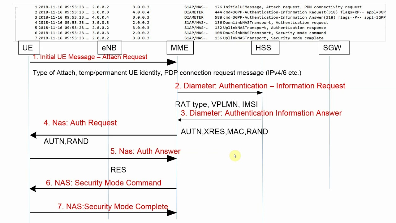
Let's walk through the pcap step-by-step. For each step, I'll describe the key messages and then direct you to a video that analyzes a similar capture, providing a narrated walkthrough of the packets you are seeing.
Step 1: The Initial Request (UE → MME)
The entire process begins when the User Equipment (UE) sends its first message to the network, which is forwarded by the eNodeB to the MME. This single message, called InitialUEMessage, kicks off the entire attach procedure. It's sent over the S1AP protocol, which you can use as a display filter in Wireshark (s1ap).
This message contains the crucial NAS Attach Request. Inside this request, the UE identifies itself (using a temporary ID like a GUTI if it has one, or requesting to use its IMSI), states its security capabilities, and includes a PDN Connectivity Request to ask for an IP address and data connection.
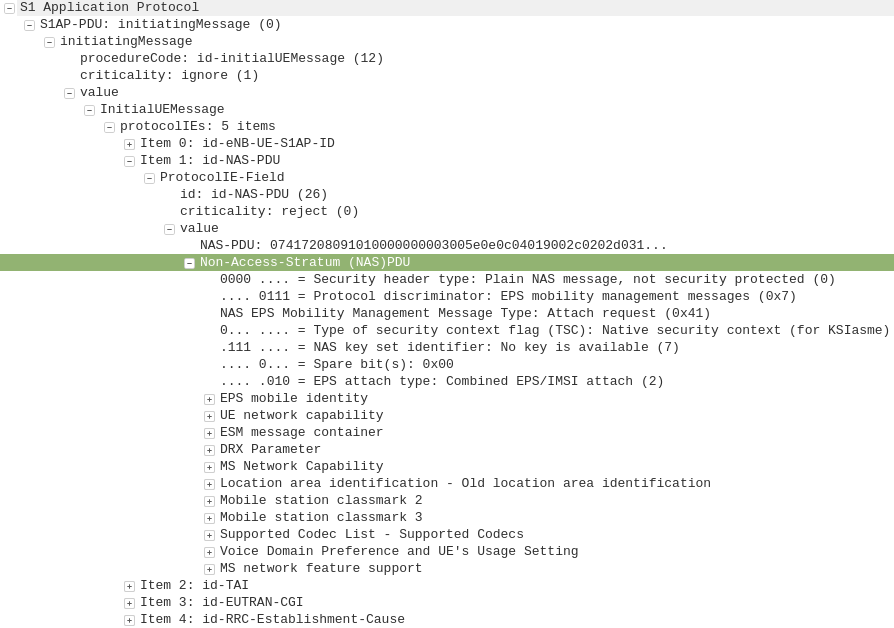
The following video segment provides a detailed analysis of this initial message.
LTE Call Flow - Wireshark (Pcap) analysis of LTE UE Attach
This video, 'LTE Call Flow - Wireshark (Pcap) analysis of LTE UE Attach' from Telco Bytes, will be our guide. Let's start with the first messages from the UE.
Watch from 02:49 to 08:52. The presenter dissects the 'Initial UE Message', explaining the key information elements like the attach type (e.g., Combined EPS/IMSI Attach) and the identifiers used. Try to find the corresponding 'InitialUEMessage' packet in your pcap2-first-attach.pcapng file.
Step 2: Authentication and Security Setup
Once the MME receives the attach request, it must authenticate the subscriber. This involves a few steps:
- MME → HSS: The MME sends a Diameter
Authentication-Information-Requestto the HSS, providing the subscriber's IMSI. - HSS → MME: The HSS responds with a Diameter
Authentication-Information-Answercontaining authentication vectors (RAND, AUTN, XRES, Kasme). - MME → UE: The MME challenges the UE with a NAS
Authentication Request, sending the RAND and AUTN. - UE → MME: The UE validates the network using the AUTN, calculates its response (RES), and sends it back in a NAS
Authentication Response. - MME: The MME compares the UE's RES with the expected XRES from the HSS. If they match, authentication is successful.
Immediately after successful authentication, the MME initiates the security procedure by sending a NAS Security Mode Command to the UE, telling it which encryption and integrity algorithms to use. The UE applies them and confirms with a Security Mode Complete. After this point, NAS signaling messages between the UE and MME will be encrypted.
LTE Call Flow - Wireshark (Pcap) analysis of LTE UE Attach
Let's continue with the video to see the authentication and security procedures in the trace.
Watch from 08:52 to 11:40. The video shows the Diameter messages (abbreviated as AIR/AIA) and the subsequent NAS authentication and security mode commands. In your pcap, filter for diameter to see the MME-HSS exchange, and then look for the NAS messages that follow.
In pcap2-first-attach.pcapng, you'll notice packet 11 is an "Authentication Failure" with a cause of "Sync Failure". As the resource LINK explains, this is normal for a brand new SIM's first attach and is part of the mechanism to synchronize sequence numbers. The actual successful authentication follows immediately after.
Step 3: Location Update and Bearer Creation (GTP-C)
With the UE authenticated, the MME gets down to business setting up the data connection.
- Update Location: The MME informs the HSS of the UE's current location by sending a Diameter
Update-Location-Request(ULR). The HSS acknowledges with anUpdate-Location-Answer(ULA). - Create Session (GTP-C): This is where our previous lesson on GTP comes to life.
- The MME sends a
Create Session Requestto the Serving Gateway (SGW) over the S11 interface. This is a GTP-C message. It contains the IMSI, the requested APN, and a TEID chosen by the MME for the control plane tunnel. - The SGW processes this, communicates with the PGW, and responds to the MME with a
Create Session Response. This message is critical: it contains the IP address allocated for the UE and the TEIDs that the SGW has allocated for the user plane data tunnel (one for uplink, one for downlink).
- The MME sends a
LTE Call Flow - Wireshark (Pcap) analysis of LTE UE Attach
The next phase involves updating the HSS and, most importantly, creating the GTP session.
Watch from 11:40 to 18:58. This covers the ESM Information Request (where the MME asks the UE for the APN), the Diameter Update Location, and the crucial 'Create Session Request' over GTP. Pay close attention to the explanation of the Tunnel Endpoint Identifiers (TEIDs) in the Wireshark trace.
In your pcap, you can filter for gtpc to isolate these GTP control messages. Find the Create Session Request and Create Session Response and see if you can locate the TEIDs and the assigned UE IP address within the packet details.
Step 4: Finalizing the Connection
The core network now has a path ready, but it needs to activate the radio bearer and inform the UE that everything is ready.
- Initial Context Setup: The MME sends a very important
Initial Context Setup Request(S1AP protocol) to the eNodeB. This message is a container for several things:- The NAS
Attach Acceptmessage, which is to be forwarded to the UE. This tells the UE its connection is approved and provides its new temporary identifier (GUTI). - The
Activate Default EPS Bearer Context Request(also NAS), which tells the UE to activate its data pipe. - The security key for the eNodeB to encrypt radio traffic (RRC and user data).
- The SGW's user plane TEID, so the eNodeB knows where to send uplink data.
- The NAS
- RRC Reconfiguration: The eNodeB reconfigures the radio link with the UE to establish the data radio bearer (DRB) and apply encryption.
- Completion: The UE confirms with
Attach CompleteandActivate Default EPS Bearer Context Accept(NAS). The eNodeB confirms withInitial Context Setup Response(S1AP). - Modify Bearer: Finally, the MME sends a
Modify Bearer Request(GTP-C) to the SGW, providing it with the eNodeB's user plane TEID. Now, the SGW knows where to send downlink data, and the end-to-end user data tunnel is fully established.
LTE Call Flow - Wireshark (Pcap) analysis of LTE UE Attach
Let's watch the final steps of the process, where the radio resources are configured and the bearer is fully activated.
Watch from 20:09 to 27:19. This covers the Initial Context Setup Request containing the piggybacked Attach Accept, and the final Modify Bearer Request that completes the tunnel setup. Try to follow this complex but critical sequence in your pcap.
At the end of this sequence, the UE has a fully functional IP connection to the internet through the LTE network.
A Glimpse into Decryption
You may have noticed in the pcap that after the Security Mode Command messages, subsequent NAS and RRC messages become encrypted and their contents are not visible in Wireshark. In our capture, which is from the core network, we see the messages between core nodes clearly. However, if we were capturing over the air, this encryption would obscure our view.
In a future module, you will build your own 4G lab using the srsRAN software suite. A key advantage of this is that the software can log the very encryption keys used for the session. With these keys, you can configure Wireshark to decrypt the RRC and user-plane traffic in real-time.
Analysing the srsRAN LTE MAC layer with Wireshark
The article 'Analysing the srsRAN LTE MAC layer with Wireshark' provides an advanced look at this process. We won't do this today, but it's important to know it's possible.
Briefly read the section titled 'Analysis in Wireshark', specifically the part about decryption that starts with: 'To decrypt the payload we need to supply the encryption key. This is done with the “PDCP UE keys…” option...'. This gives you a preview of the powerful analysis capabilities we will unlock once we have our own test lab running.
This ability to decrypt traffic is fundamental to deep security analysis and is a key skill you'll develop later in the course.
Conclusion
In this lesson, you have bridged the gap between theory and practice by dissecting a real LTE attach procedure. By navigating a pcap with Wireshark, you've seen firsthand how high-level concepts are implemented through a precise sequence of signaling messages.
Key Takeaways:
- The attach procedure is a well-defined sequence of S1AP, Diameter, and NAS messages.
- The
InitialUEMessagefrom the UE kicks off the process, carrying the NASAttach Request. - Authentication involves a three-way conversation between the UE, MME, and HSS.
- The NAS
Security Mode Commandis the point where signaling encryption is enabled. - Bearer setup is handled by GTP-C messages (
Create Session Request/Response), which are used to exchange TEIDs and establish the data tunnels. - The
Initial Context Setup Requestis a key message from the MME to the eNodeB that carries the final NASAttach Acceptto the UE and activates the radio bearer.
Preview of the Next Lesson:
Now that you can identify the major messages in the attach flow, our next step is to zoom in. In the next lesson, we will focus on how to identify key information elements within RRC and NAS messages in a capture. You will learn to pinpoint specific pieces of data—like the UE's requested APN, its security capabilities, and the network's timer settings—within the detailed structure of these protocol messages.