Hello! Welcome back.
In our last session, we formally defined the isentropic process as the "perfect" process—one that is both completely insulated (adiabatic) and perfectly smooth (reversible). The beautiful result of this perfection is that the entropy of the substance doesn't change at all (). We saw this as a straight vertical line on our T-s diagrams.
Today, we're going to put that ideal benchmark to practical use. Our goal is to analyze ideal turbines, compressors, and nozzles. We will learn how to calculate the theoretical best-case performance for these crucial engineering devices. This means finding the maximum possible work we can get out of a turbine, or the minimum possible work we need to put into a compressor.
We'll tackle this in two ways: first, using the isentropic relations for ideal gases (which you've seen before), and second, using property tables for real substances like steam. This lesson is all about connecting the abstract concept of constant entropy to the concrete numbers that engineers use every day.
The General Toolkit: SFEE and the Isentropic Assumption
Remember the Steady-Flow Energy Equation (SFEE) from Module 5? It's our master equation for analyzing devices with fluid flowing through them. Let's write it down again (on a per-unit-mass basis, using for work and for heat):
Where:
- = heat transferred into the system
- = work done by the system
- = specific enthalpy (the total energy of the flowing fluid)
- = velocity
- = height
For the devices we're studying today (turbines, compressors, nozzles), the change in height is almost always negligible, so we can ignore the term.
Now, here's the key: we are analyzing ideal devices. As we learned, an ideal process in these devices is an isentropic one. This gives us two powerful simplifications:
- Adiabatic: The process is perfectly insulated, so there is no heat transfer. This means .
- Reversible: The process is perfectly smooth with no friction, which means the entropy remains constant: .
This second point, , is the magic key that unlocks the whole analysis. It provides the crucial piece of information we need to pinpoint the exact exit state of the fluid.
Let's see how this works for each device.
Analyzing an Ideal (Isentropic) Turbine
A turbine is like a windmill for high-energy fluid. Its job is to extract energy from a flowing fluid (like steam or hot gas) and convert it into rotational work, like turning an electricity generator.
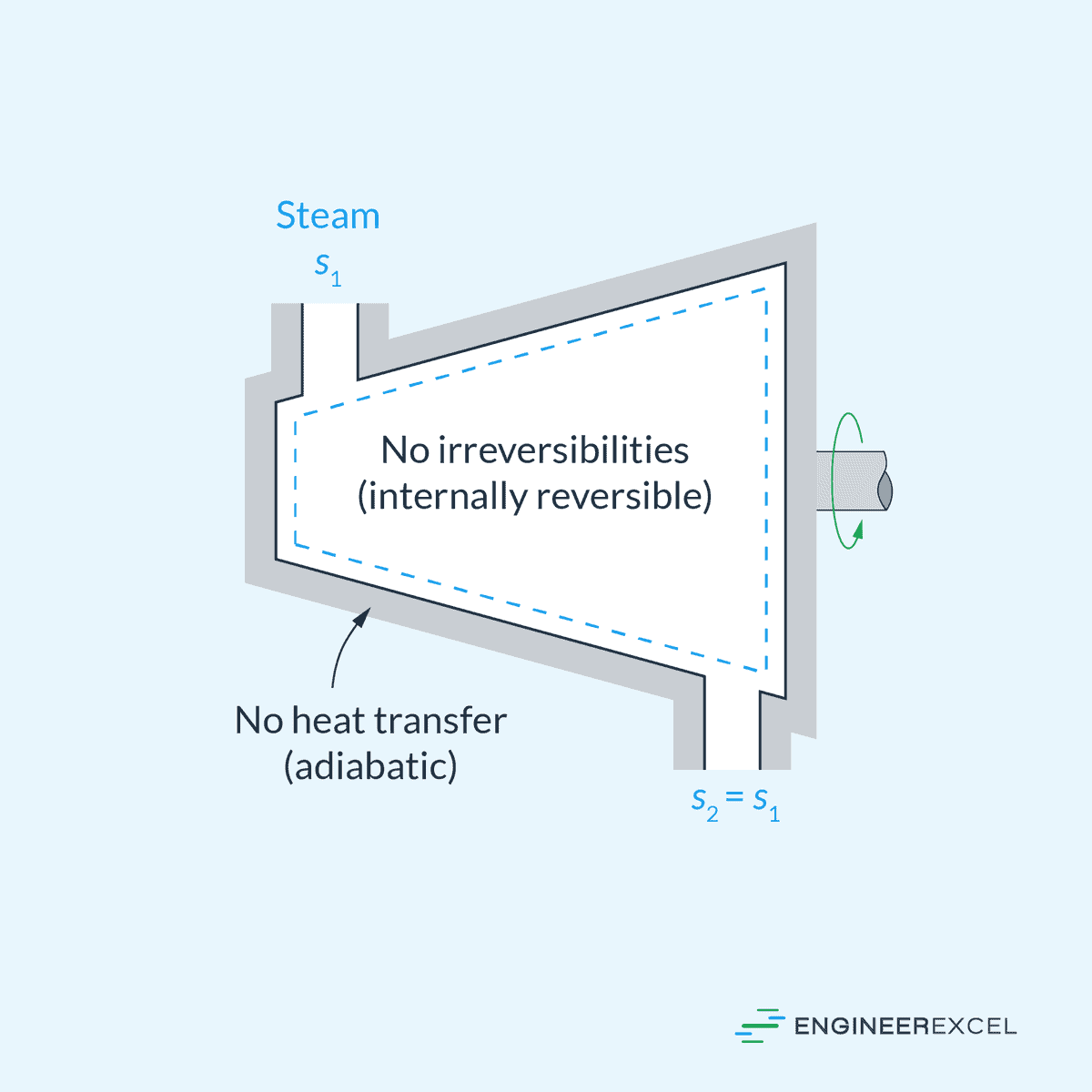
Let's simplify the SFEE for our ideal turbine:
- (it's adiabatic).
- For turbines, the change in kinetic energy is usually tiny compared to the change in enthalpy, so we'll assume .
The SFEE boils down to:
To show that we're talking about the ideal, isentropic case, we'll label the exit state with an 's'. So, the ideal work output is:
The big question is: How do we find ?
We typically know the inlet conditions (State 1: , ) and the pressure the turbine exhausts to (State 2: ). That's not enough to know the enthalpy . But since the process is isentropic, we have our magic key:
So, the ideal exit state (State 2s) is fixed by two properties: the known exit pressure and the entropy from the inlet.
Example 1: An Ideal Steam Turbine (Using Property Tables)
Let's analyze a steam turbine. Steam is a "real substance," so we have to use steam tables. This process is fantastically illustrated on an enthalpy-entropy (h-s) diagram, also called a Mollier chart.
To learn about this chart and see how it visually represents our turbine process, please read the following material.
This article from Spirax Sarco explains the Mollier chart (h-s diagram). It's a graphical form of the steam tables and is perfect for visualizing processes like the one in our turbine.
Please read the section titled 'The Mollier chart'. Focus on understanding what the different lines represent (constant pressure, constant temperature, and the saturation curve). Notice that a 'perfect expansion' in a turbine is a straight vertical line moving downwards—this is our isentropic process!
Now, let's solve a problem.
Problem: Superheated steam enters an ideal turbine at 5 MPa and 400°C. It expands to a pressure of 40 kPa. What is the work output of the turbine per kg of steam?
Solution:
Step 1: Find properties at the inlet (State 1).
We are given and . We go to the superheated steam tables.
Looking up at P = 5.0 MPa, we find the row for T = 400°C.
- Enthalpy:
- Entropy:
Step 2: Use the isentropic condition to define the ideal exit state (State 2s).
We know the exit pressure is . The magic key for an ideal turbine is that entropy is constant:
So, State 2s is defined by: and .
Step 3: Find the enthalpy at the ideal exit state (h_2s).
We go to the saturated steam tables at . We need to figure out if the steam at the exit is still superheated, a saturated mixture, or a compressed liquid.
At 40 kPa, we find the entropies for saturated liquid () and saturated vapor ():
Our entropy, , is between and . This tells us the steam at the exit is a saturated liquid-vapor mixture. We need to find its quality, .
Recall the formula: , where .
at 40 kPa is .
Solving for :
This means the steam at the ideal exit is 84.6% vapor.
Now we can find the enthalpy using the same quality:
From the table at 40 kPa: and .
Step 4: Calculate the ideal work output.
This is the maximum possible energy we can extract from each kilogram of steam under these conditions. A real turbine would have friction and produce less work.
To see this exact type of calculation performed using both the tables and a Mollier chart, you can review the following example.
Example of perfect isentropic expansion
This is the same Spirax Sarco resource, but now we're looking at a specific worked example that mirrors what we just did.
Read 'Example 2.3.6 Perfect isentropic expansion resulting in work'. Follow their steps for using the steam tables. You'll see they follow the exact same logic: find s1, set s2=s1, find the quality x2, and then find h2.
Analyzing an Ideal (Isentropic) Compressor
A compressor does the opposite of a turbine: it takes in work to increase the pressure of a fluid. Think of an air compressor filling a tank or the compressor in your refrigerator.

The simplified SFEE for an ideal compressor is:
For the ideal (isentropic) case, this becomes:
The logic is identical to the turbine, just in reverse. We know the inlet state () and the desired outlet pressure (). We use our magic key, , to find the ideal exit enthalpy and thus the minimum work required.
Example 2: An Ideal Air Compressor (Using Ideal Gas Relations)
Problem: Air enters an ideal compressor at 100 kPa and 25°C. It is compressed to 800 kPa. What is the minimum work input required? (For air, use and ).
Solution:
Step 1: Convert temperature to Kelvin.
A crucial step whenever using ideal gas laws!
Step 2: Use the isentropic relation to find the ideal exit temperature (T_2s).
For an ideal gas undergoing an isentropic process, you'll recall this relation from Module 4:
Let's calculate the exponent: .
The air gets very hot during this ideal compression, reaching 540 K (or 267°C)!
Step 3: Calculate the ideal work input.
For an ideal gas, the change in enthalpy is simply .
This is the absolute minimum work needed to compress the air to the target pressure.
Test your understanding!
Question: In the steam turbine example, the temperature dropped significantly. In the air compressor example, the temperature rose significantly. Why? What fundamental principle connects these two observations?
Show answer
This goes back to the First Law of Thermodynamics for adiabatic processes ().
For the turbine, the system is doing work (). Since no heat can come in to provide the energy, the work must be done by drawing from the fluid's own internal energy. A drop in internal energy corresponds to a drop in temperature.
For the compressor, work is being done on the system (). This energy is added to the fluid. Since no heat can escape, the energy gets trapped, increasing the fluid's internal energy and therefore its temperature. This is why a bicycle pump gets hot when you use it.
Analyzing an Ideal (Isentropic) Nozzle
A nozzle is a simple device with a carefully shaped passage designed to do one thing: accelerate a fluid. It converts the fluid's enthalpy (pressure and temperature) into kinetic energy. There is no work done in a nozzle ().
Let's simplify the SFEE for our ideal nozzle:
- (adiabatic).
- (no work).
- Often the inlet velocity is very small compared to the exit velocity , so we can assume .
The SFEE becomes:
Solving for the exit velocity :
Look familiar? The calculation for the enthalpy drop, , is exactly the same as for an ideal turbine operating between the same two pressures! The only difference is where the energy goes. In a turbine, it becomes shaft work. In a nozzle, it becomes kinetic energy.
Example 3: An Ideal Steam Nozzle
Problem: Steam at 5 MPa and 400°C enters an ideal nozzle and expands to 40 kPa. What is the exit velocity of the steam?
Solution:
This is easy! The steam conditions are identical to our turbine example. We already did the hard work.
- From Step 1 in the turbine example, .
- From Step 3, we found that for an isentropic expansion to 40 kPa, .
Now we just plug these into the nozzle velocity equation.
Important: The enthalpy values are in kJ/kg. To get velocity in m/s, we must convert kJ to J by multiplying by 1000. The units work out as: .
That's over 3000 miles per hour! This shows the immense energy stored in high-pressure steam and how effectively a nozzle can convert it to speed.
Summary of Key Takeaways
Fantastic work today. We've taken the theoretical concept of an isentropic process and turned it into a powerful, practical calculation tool.
- The analysis of ideal (isentropic) turbines, compressors, and nozzles starts with the Steady-Flow Energy Equation (SFEE).
- The isentropic assumption () is the key piece of information that allows us to determine the ideal exit state of the fluid.
- The general procedure is:
- Find the enthalpy () and entropy () at the known inlet state.
- The ideal exit state is defined by the known exit pressure () and the entropy ().
- Use these two properties to find the ideal exit enthalpy (), either from property tables (for substances like steam) or by using ideal gas relations ( and then ).
- The enthalpy change or then gives you the ideal work or is used to find the ideal exit velocity.
Preview of the Next Lesson
We have now mastered calculating the "perfect" performance. But no real device is perfect. The logical next question is, "How good is my actual device compared to this ideal benchmark?"
In the next lesson, we will introduce the concept of isentropic efficiency. This is a simple ratio that compares the actual work output of a turbine (or work input to a compressor) to the ideal, isentropic work we calculated today. This will finally allow us to bridge the gap between our perfect theoretical models and the performance of real-world hardware.