Introduction
Welcome to the next lesson in our PCIe deep dive. In the previous lesson, we explored how the IOMMU provides essential DMA security and enables high-performance device passthrough for virtualization. We now have a solid understanding of how PCIe devices are discovered, configured for memory access, signal interrupts, and perform secure data transfers.
However, in the world of embedded systems, performance and security must be balanced with power efficiency. A high-speed device that drains the battery when idle is often impractical. This brings us to the crucial topic of power management on the PCIe bus.
This lesson will focus on a key mechanism called Active State Power Management (ASPM). Our goal is to learn how to configure and observe PCIe device power management (ASPM) state transitions. We will investigate the different power-saving link states, see how the Linux kernel manages them, and learn the tools to verify that our power-saving policies are actually taking effect.
1. The Two Faces of PCIe Power Management: Device vs. Link
Before we dive into ASPM, it's important to distinguish between the two levels of power management in the PCIe world.
- Device Power Management (PCI-PM): This concerns the overall power state of the entire device. These are the familiar
Dstates (D0, D1, D2, D3hot, D3cold). D0 is the fully-on state, while D3cold is the fully-off state where main power is removed. These state changes are typically driven by the device driver when the device is opened, closed, or suspended. - Link Power Management (ASPM): This is a more granular, dynamic power management for the physical link between two PCIe components (e.g., a root port and an endpoint). It saves power when the link is idle, even if the device itself is in the D0 (fully on) state.
This lesson focuses exclusively on ASPM and the link power states, which are designated with an L.
2. A Tour of the PCIe Link States
The fundamental principle of ASPM is the trade-off between power savings and recovery latency. The deeper the power-saving state, the longer it takes for the link to become active again.
To understand these states and their relationships, let's consult a helpful overview.
How are PCIe Low Power L1 Sub-states achieved using ASPM
The NXP Tech Blog article 'How are PCIe Low Power L1 Sub-states achieved using ASPM' provides a clear breakdown of the various link states. We'll start by reading the first two sections to build our foundational knowledge.
Please read the sections titled 'Introduction to PCIe power management' and 'What are L1 sub-states and where do they fall inside the LTSSM?'. Focus on understanding the hierarchy of the L-states and the fundamental trade-off between power savings and recovery latency.
Based on that reading, here is a summary of the key states, from most power-hungry to most efficient:
- L0 (Active): The normal, active state where data is being transferred.
- L0s (Standby): A light power-saving state. The physical layer is partially shut down, but the transition back to L0 is very fast. Support for L0s is optional for most devices.
- L1: A deeper power-saving state than L0s, offering more savings but with a longer recovery time. Both the link and transaction layers are deactivated.
- L1 Sub-states (L1.1 and L1.2): These are optional, even deeper sleep states that build upon L1. They achieve significant power savings by turning off common-mode voltage keepers (L1.1) and even the main reference clock (L1.2). The ability to turn off the clock is a major power-saver in embedded systems.
- L2/L3: The deepest sleep states, where main power to the device may be removed. These are typically entered as a consequence of the device entering a D3 power state.
The transition between these states is managed by a state machine called the LTSSM (Link Training and Status State Machine).
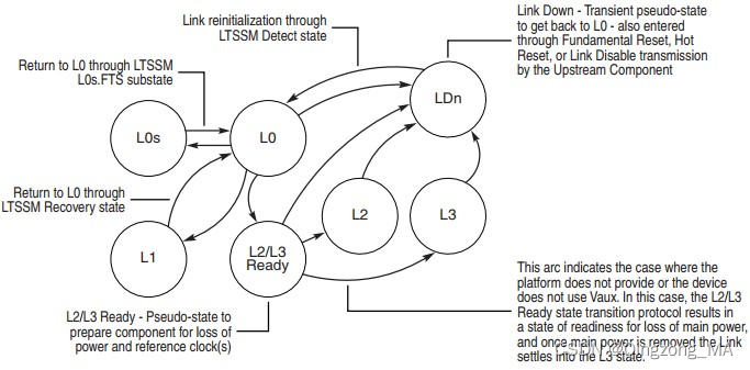
3. Observing ASPM Status in Linux
Now for the practical part: how do you know if ASPM is working on your system? The primary tool for this is lspci, which you have used before. The -vvv flag provides maximum verbosity, decoding the PCIe capability registers for us.
Let's see what to look for.
ASPM on Linux — Linux Wireless documentation
The Linux Wireless documentation page on ASPM provides excellent, concise examples of how to interpret lspci output. We will also use a section from the NXP article to see another example.
Please read the section 'Determining if you have ASPM enabled', focusing on the lspci -vvv output for both enabled and disabled cases.
When you run lspci -vvv on a device, you need to inspect the LnkCap (Link Capabilities) and LnkCtl (Link Control) fields within the PCI-Express capabilities section.
LnkCap: This tells you what the hardware supports. You'll see which ASPM states (e.g., L0s, L1) the device is capable of.LnkCtl: This tells you what is currently enabled. This is what the kernel has configured.
Here is an example, similar to the one in the NXP article:
# lspci -s 04:00.0 -vvv
04:00.0 Ethernet controller: Intel Corporation I210 Gigabit Network Connection
        ...
        Capabilities: [80] PCI-Express: Endpoint, MSI-X ...
                ...
                LnkCap: Port #0, Speed 2.5GT/s, Width x1, ASPM L0s L1, Exit Latency L0s <1us, L1 <4us
                        ClockPM- Surprise- LLActRep- BwNot- ASPMOptComp+
                LnkCtl: ASPM L1 Enabled; RCB 64 bytes, Disabled- CommClk+
                        ExtSynch- ClockPM- AutWidDis- BWInt- AutBWInt-
        ...
In this output:
LnkCapshowsASPM L0s L1, meaning this Intel I210 network card supports both L0s and L1 states.LnkCtlshowsASPM L1 Enabled, meaning the kernel has successfully enabled the L1 state. L0s is supported but not currently enabled in this configuration.
It's crucial to remember that ASPM is a negotiation. Both the downstream component (the device/endpoint) and the upstream component (the root port or switch port it's connected to) must support and agree on the ASPM state. If one side doesn't support L1, the link cannot enter L1.
4. Configuring ASPM in the Linux Kernel
If lspci shows ASPM is disabled, how do you enable it? The Linux kernel provides a centralized policy mechanism via sysfs.
How are PCIe Low Power L1 Sub-states achieved using ASPM
The NXP article gives a direct, practical guide on how to configure ASPM policy in a modern Linux kernel.
Read the section 'How is ASPM exercised in linux kernel?'. Pay close attention to the kernel configuration options and the sysfs file used to set the policy.
As the article explains, there are two main steps:
Step 1: Kernel Configuration
Your kernel must be compiled with ASPM support. The key options in your Kconfig are:
CONFIG_PCIEASPM=y: This enables the core ASPM framework.CONFIG_PCIEASPM_PERFORMANCE=y,CONFIG_PCIEASPM_POWERSAVE=y,CONFIG_PCIEASPM_POWER_SUPERSAVE=y: These enable the different policy levels.POWER_SUPERSAVEis the most aggressive, enabling L1 sub-states where supported.
Step 2: Runtime Policy Configuration
The active policy is controlled via a single file in sysfs:/sys/module/pcie_aspm/parameters/policy
You can inspect the current policy:
$ cat /sys/module/pcie_aspm/parameters/policy
[default] performance powersave powersupersave
The entry in brackets ([default]) is the currently active policy. To change it, you write one of the other values to the file as root:
# To prioritize power savings
echo "powersave" > /sys/module/pcie_aspm/parameters/policy


# To be even more aggressive and enable L1 substates
echo "powersupersave" > /sys/module/pcie_aspm/parameters/policy


# To prioritize performance and disable ASPM
echo "performance" > /sys/module/pcie_aspm/parameters/policy
After changing the policy, you can re-run lspci -vvv to observe the change in the LnkCtl register.
For debugging or overriding a buggy BIOS, the kernel also provides a boot parameter: pcie_aspm.
pcie_aspm=off: Globally disables ASPM.pcie_aspm=force: Forcibly enables ASPM on all links that support it, overriding any BIOS settings.
5. How State Transitions Really Work
Setting a policy in sysfs is a high-level command. What happens on the wire to make the link enter a low-power state? The process involves a handshake using Data Link Layer Packets (DLLPs) and, for L1 sub-states, a special sideband signal.
- Initiation: When the link has been idle, the downstream port (the device) begins sending
PM_Active_State_Request_L1DLLPs to the upstream port. - Acknowledgement: The upstream port acknowledges the request with a
PM_Request_AckDLLP. - Entering L1: Both sides stop transmitting, and the link enters the L1 state.
- Entering L1 Sub-states (L1.1/L1.2): This is the key part for deep power savings. After entering L1, the device de-asserts the
CLKREQ#signal. This is a physical sideband signal that tells the platform it no longer needs the PCIe reference clock. The clock source can now be shut down, saving significant power. - Exiting: To exit, the device re-asserts
CLKREQ#, the platform restores the clock, and the link undergoes a fast recovery training sequence to return to the L0 state.
This flowchart visualizes the entry process from the perspective of the Linux driver and the hardware.

6. Interview Scenario
Interviewer: "You're working on a battery-powered embedded Linux device that uses a PCIe-based WiFi module. The battery life is much shorter than specified, and you suspect that the PCIe link is not entering its low-power states correctly when idle. How would you systematically diagnose this problem?"
Click for Analysis
This is a classic embedded systems problem that tests your ability to connect high-level software configuration with low-level hardware behavior.
Your Diagnostic Steps:
-
Baseline Observation: The first step is to verify the current state. I would run
lspci -s <wifi_bdf> -vvvon the WiFi module and its upstream root port. I'd check theLnkCapto confirm both sides support ASPM L1, andLnkCtlto see what is currently enabled. A mismatch here is a primary clue. -
Check Kernel Configuration: I'd verify that the running kernel was built with
CONFIG_PCIEASPM=yandCONFIG_PCIEASPM_POWER_SUPERSAVE=y. I'd check this in/proc/config.gzor the kernel's.configfile. If not, the kernel needs to be recompiled. -
Check Runtime Policy: I'd run
cat /sys/module/pcie_aspm/parameters/policy. If it's set toperformanceordefault, that's a likely culprit. I wouldecho "powersupersave"into the file to enable the most aggressive power savings and then re-runlspci -vvvto see ifLnkCtlchanges toASPM L1 Enabled. -
Inspect Kernel Logs: I would check
dmesg | grep -i aspmfor any errors or warnings from the PCIe subsystem. The kernel might be logging that it can't enable ASPM on a link for a specific reason (e.g., a known hardware bug or incompatibility). -
Test BIOS/Firmware Override: If the policy is set to
powersavebut ASPM is still not enabling, I would suspect the BIOS is disabling it. I would reboot the system with the kernel boot parameterpcie_aspm=forceto see if the kernel can successfully override the BIOS. -
Advanced Debugging (Mentioning this shows deep expertise): If all else fails, it's possible there is a subtle hardware or driver issue. I would mention that I could use
setpcito directly read the Link Control register from the device's configuration space to be absolutely certain of its state, independent oflspci's parsing. This would confirm if the kernel's attempt to write to the register is actually sticking. If I had access to a PCIe bus analyzer, I could physically probe the link to see if thePM_Active_State_Request_L1DLLPs are being sent and if theCLKREQ#signal is being de-asserted.
Conclusion
In this lesson, we've demystified PCIe Active State Power Management. You now understand the difference between device and link power states, the hierarchy of L-states, and the critical trade-off between power savings and latency. Most importantly, you have the practical knowledge to configure and observe these states in a running Linux system.
Key Takeaways:
- ASPM manages the power of the PCIe link, complementing the D-states which manage the device.
- The link states (L0, L0s, L1, L1.1, L1.2) offer a spectrum of power savings versus recovery latency. L1 sub-states are key for deep power savings by allowing the reference clock to be gated.
- The
lspci -vvvcommand is your primary tool for observing ASPM capabilities (LnkCap) and current configuration (LnkCtl). - The kernel's ASPM policy, set via
/sys/module/pcie_aspm/parameters/policy, is the standard way to configure ASPM behavior.
The tools we've used here, lspci and setpci, are indispensable for any low-level PCIe work. In our next and final lesson of this module, we will broaden our focus and see how to use these utilities, along with kernel log analysis, to debug a PCIe device initialization failure, tackling a common and challenging problem in embedded development.