Welcome back! In our last lesson, we established the theoretical foundation for good database design, exploring keys, relationships, and the rules of normalization up to the Third Normal Form (3NF). You learned why structuring data correctly is crucial for integrity and scalability. Now, we'll shift from theory to practice.
This lesson is about applying those principles to a real-world problem. Your goal is to design the logical blueprint for a database that could power a system like Infilect's. We'll start with a simple set of requirements for a retail analytics platform and translate them into a formal Entity-Relationship Diagram (ERD). This process is fundamental for any backend engineer, especially when building systems that handle complex, interconnected data for analytics and machine learning.
By the end of this lesson, you will be able to:
- Extract key entities and attributes from a set of business requirements.
- Determine the relationships and cardinality (one-to-many, many-to-many) between entities.
- Design a normalized ERD using Crow's Foot notation.
- Resolve many-to-many relationships using junction tables.
1. From Business Need to Data Model
Imagine you're a backend engineer at a company like Infilect. A product manager gives you a high-level overview of a new "Smart Shelf" monitoring system. The goal is to use images from stores to track product availability and placement.
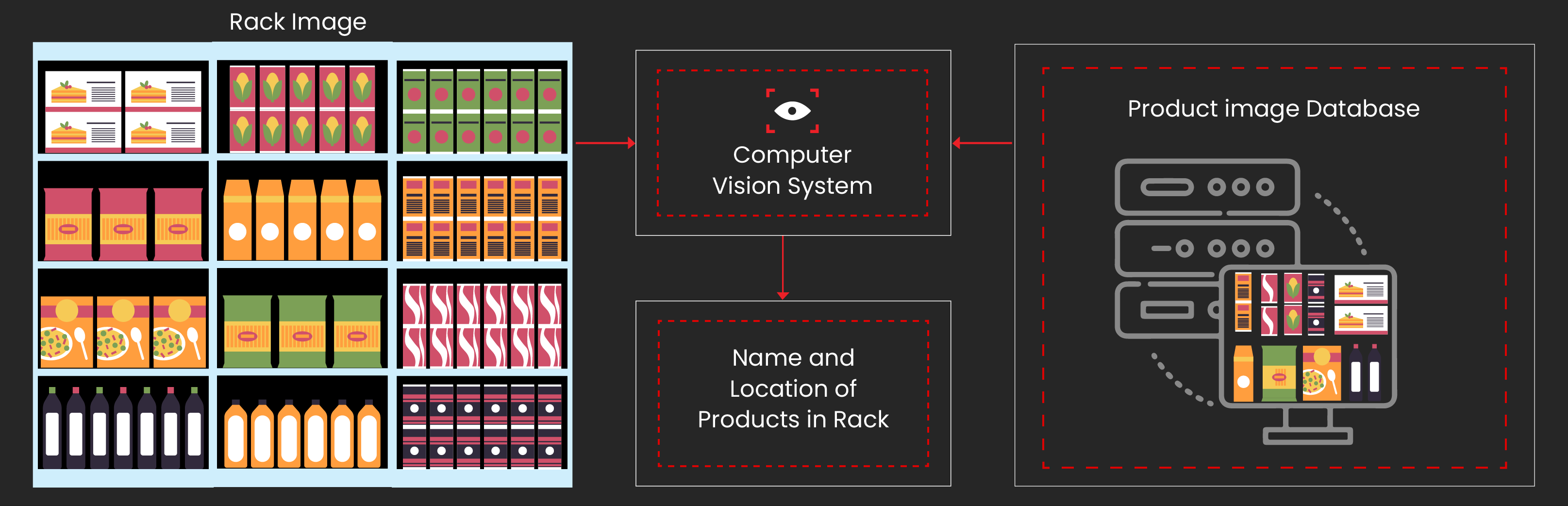
Our task is to design the database that underpins this entire process. Before we can write any code (like Django models), we need a blueprint. This blueprint is the Entity-Relationship Diagram (ERD).
So, where do we begin? The first step is to analyze the requirements of the system. Let's imagine our simplified system needs to do the following:
"Our system needs to track multiple stores. For each store, we need to know its name and location. We sell various products, each having a name, a description, and a standard price. Products are grouped into categories, like 'Beverages' or 'Snacks'. Periodically, we receive shelf images from each store. An ML model analyzes these images to identify which products are visible. We need to store the results of this analysis, specifically, which products were found in which image, along with their coordinates (e.g., an x,y bounding box). Finally, we also track sales transactions. A single sale can include multiple products and their quantities."
2. Identifying Entities and Relationships
A powerful technique for starting a data model is to read through the requirements and identify the nouns and verbs. Nouns often become our entities (tables) or attributes (columns), while verbs suggest the relationships between them.
The following video provides an excellent walkthrough of this process, along with an introduction to ERDs and the popular Crow's Foot notation we'll be using.
This video from Decomplexify demonstrates how to turn a set of requirements into a logical data model by identifying entities, defining relationships, and determining cardinality.
Please watch these key segments: From requirements to entities: See how nouns are extracted from a problem description to identify potential entities and relationships. Cardinality of relationships: Understand how to ask critical questions to define the "how many" aspect of each relationship (e.g., can a pet have more than one owner?). Crow's Foot notation: Learn the symbols for this widely-used ERD notation, which clearly visualizes one-to-one, one-to-many, and many-to-many relationships.
From our requirements, the key nouns are: Store, Product, Category, Shelf Image, Sale, and the result of the image analysis (the link between an Image and a Product).
Now, how do we decide which of these become entities (tables) and which become attributes (columns)? A helpful guide is to ask a few questions about each noun. If you can answer "yes" to two or more, it should likely be an entity.
Entity Relationship Diagram and Database Normalization Process
This article from Chosen Gambit provides a structured way to think about modeling.
Read the sections Entity or Attribute and Processing Nouns. This will give you a clear set of criteria for deciding whether a noun should be a table or just a field within a table.
Applying this logic to our nouns:
- Store: We want to store multiple stores. Each has its own identity and attributes (name, location). It will be referenced by other entities (images, sales). This is an entity.
- Product: Same logic. We'll have many products, each with its own ID, name, price, etc. This is an entity.
- Category: We'll have multiple categories, and they group products. This is an entity.
- Shelf Image: We'll ingest many images. Each has its own data (timestamp, file path) and is linked to a store. This is an entity.
- Sale: We'll track many sales transactions. Each has a date and is linked to a store. This is an entity.
3. Defining Cardinality and Resolving Many-to-Many
Now that we have our entities, we need to define the relationships between them using the Crow's Foot notation you just learned about. Let's think through the connections.
- Category to Product: A category can have many products, but a product belongs to just one category. This is a one-to-many (1:N) relationship. (
Categoryis the "one" side,Productis the "many" side). - Store to Shelf Image: A store can have many shelf images taken over time, but each image belongs to exactly one store. This is a one-to-many (1:N) relationship.
- Store to Sale: A store can have many sales, but a sale occurs at exactly one store. This is a one-to-many (1:N) relationship.
Now for the trickier ones.
- Sale to Product: A single sale can include many different products (e.g., milk, bread, eggs). A single product can be part of many different sales over time. This is a many-to-many (M:N) relationship.
- Shelf Image to Product: A single shelf image can contain many different products. A single product can appear in many different images. This is also a many-to-many (M:N) relationship.
Relational databases cannot directly implement M:N relationships. We need to introduce an intermediary table, often called a junction or link table.
Let's revisit the Decomplexify video for a clear explanation of how to resolve this.
Watch the final segment on handling many-to-many relationships. The video explains how to break down an M:N relationship into two 1:N relationships using a new junction entity.
To resolve our M:N relationships, we'll create:
- A
SaleItemtable: This will linkSaleandProduct. Each row will represent one line item in a sale, containing a foreign key toSale, a foreign key toProduct, and additional attributes likequantityandprice_at_time_of_sale. - An
ImageAnnotationtable: This will linkShelfImageandProduct. Each row will represent one detected product in an image, containing a foreign key toShelfImage, a foreign key toProduct, and thebounding_boxcoordinates.
4. Assembling the ERD for our Retail System
Let's combine everything into our final ERD blueprint. Below is a textual representation of the entities, their key attributes, and the relationships.
Entities and Attributes:
- Category
id(PK)name
- Product
id(PK)category_id(FK to Category)namedescriptionstandard_price
- Store
id(PK)namelocation
- Sale
id(PK)store_id(FK to Store)sale_timestamp
- SaleItem (Junction Table)
id(PK)sale_id(FK to Sale)product_id(FK to Product)quantityprice_at_time_of_sale
- ShelfImage
id(PK)store_id(FK to Store)image_urlcapture_timestamp
- ImageAnnotation (Junction Table)
id(PK)image_id(FK to ShelfImage)product_id(FK to Product)bounding_box(e.g., JSON field with x1, y1, x2, y2)
This structure is in Third Normal Form (3NF). Each piece of non-key information depends on "the key, the whole key, and nothing but the key," just as we learned in the previous lesson. For example, a product's name is stored only once in the Product table, not repeated in every sale it's a part of.
For a complete visual example of an ERD for a similar retail system, you can review the diagram in the following article.
How to Design ER Diagrams for Point of Sale (POS) Systems - GeeksforGeeks
This GeeksforGeeks article provides a full ERD for a Point of Sale system. While their model is slightly different (e.g., it includes Suppliers and Employees), it's a great reference to see how these concepts are visualized.
Focus on the diagram under the heading Representation of ER Diagram. Compare its structure to the one we've just designed. Notice how they also use junction tables (though they may not be explicitly named as such) to handle M:N relationships.
5. The Normalization Trade-Off
Our normalized (3NF) design is excellent for writing data and ensuring consistency. This type of system is often called an Online Transaction Processing (OLTP) system. It's optimized for fast writes, updates, and deletes without risking data integrity.
However, what if a data analyst wants to run a complex query, like "What is the total monthly revenue for each product category across all stores in the 'North' region?" Answering this requires joining many tables (SaleItem -> Sale -> Store and SaleItem -> Product -> Category). On huge datasets, these joins can be slow.
This is where the concept of denormalization comes in. For analytics, systems are often designed to be faster for reads, even if it means introducing some data redundancy. These are called Online Analytical Processing (OLAP) systems.

For the Infilect role, it's vital to understand both. You'll build normalized backend systems for data ingestion and management (OLTP), but you'll also design systems that must serve data to analytics dashboards (OLAP). For now, mastering normalization is the priority.
Conclusion
In this lesson, you've bridged the gap between abstract theory and concrete design. You took a set of requirements for a retail intelligence system and systematically transformed them into a logical, normalized data model represented by an ERD.
Key Takeaways:
- ERDs are blueprints: They are an essential first step in database design, allowing you to plan your data structure before writing any code.
- Nouns and Verbs are your guides: Analyzing requirements helps you identify potential entities, attributes, and relationships.
- Cardinality is key: Defining relationships as one-to-one, one-to-many, or many-to-many dictates the structure of your database.
- Junction tables resolve M:N: The many-to-many relationship is handled by creating an intermediate table that has a one-to-many relationship with the two original entities.
- Normalization has trade-offs: A 3NF design is ideal for data integrity (OLTP), but denormalization is often used to optimize for read-heavy analytics (OLAP).
You now have a complete blueprint for the database of our "Retail Inventory API" project. In the next lesson, we will bring this blueprint to life by translating these entities and relationships into actual Django models.