Welcome to your first hands-on lesson in electronics! In our last session, we demystified circuit schematics, learning to read them as the universal blueprints of electronics. We finished by analyzing a simple diagram for an LED circuit. Today, you'll bring that diagram to life. This is the moment where theory meets practice, a pivotal step towards your goal of building robotics and IoT systems.
This lesson is your "Hello, World!" for hardware. You will learn how to use a solderless breadboard to build and test that very same LED circuit. We'll cover how a breadboard works, why the resistor in the circuit is so crucial, how to calculate its value, and then walk through the physical assembly step-by-step. By the end of our session, you will have successfully translated an abstract schematic into a functioning electronic device.
The Prototyping Canvas: The Breadboard
Before you can build a circuit, you need a canvas. In electronics, for prototyping, that canvas is the solderless breadboard. It allows you to create and modify circuits quickly without any permanent connections, much like how you might use an interactive shell or REPL to test code snippets before committing them to a larger program.
To get a complete overview of how a breadboard is constructed and how its internal connections work, the following video from Science Buddies is an excellent starting point.
This video provides a clear, visual introduction to breadboards, from their purpose and variations to their internal wiring.
Please watch the following segments: Introduction: What a breadboard is and its common sizes. Internal Connections: A look inside the breadboard at the metal clips that make connections. Layout and Connectivity: An explanation of the row/column labels, the power buses (rails), and how the holes are electrically connected.
To summarize the key points from the video:
- Terminal Strips: The main area of the breadboard has rows of holes. The five holes in each half-row (e.g., A1 through E1) are electrically connected by a metal clip.
- Ravine: A central gap separates the two sides of the terminal strips. This is crucial for placing integrated circuits (which we'll see later) and ensuring the two sides of a component are not shorted together.
- Power Rails (Buses): The long strips running down the sides, usually marked with '+' and '–', are for distributing power. All holes in a power rail are connected together. This provides easy access to your power source from anywhere on the board.
If you prefer a textual reference, the "Anatomy of a Breadboard" section in the SparkFun guide below covers the same concepts with helpful diagrams.
This guide from SparkFun is a great written resource that you can bookmark for future reference. It breaks down the internal workings of a breadboard.
Read the section titled Anatomy of a Breadboard. Focus on how the terminal strips and power rails are connected internally.
The LED: Why It Needs a Guardian Resistor
Now let's turn to the components. An LED (Light-Emitting Diode) is a semiconductor device that emits light when current flows through it. Unlike a simple resistor, an LED has polarity—it only works in one direction. The longer leg is the positive terminal, called the anode, and the shorter leg is the negative terminal, the cathode.
A critical property of LEDs is their relationship between voltage and current. It's not a simple linear relationship like a resistor's. The following video from Ben Eater explains this brilliantly and demonstrates why connecting an LED directly to a power source is a recipe for disaster.
Limiting current through an LED | Digital electronics (2 of 10)
This video explains the electrical characteristics of an LED and the fundamental reason a current-limiting resistor is necessary.
Watch the first two minutes, from the start to the end of the explanation of the V-I curve. This will give you the core intuition for why we need to control the current through an LED, not just the voltage across it.
As you saw, a small increase in voltage across an LED can cause a massive, destructive surge in current. The current-limiting resistor's job is to "absorb" the excess voltage and, by Ohm's Law, set the current to a safe level for the LED.
Calculating the Resistor Value
So, how do we choose the right resistor? We can calculate the required value using concepts you're already familiar with: Ohm's Law and voltage drops in a series circuit.
The key equation is:
Where:
- is the resistance of our current-limiting resistor.
- is the source voltage (e.g., 5V from your power supply).
- is the LED's forward voltage, which is the voltage drop across the LED when it's on. This value depends on the LED's color and can be found in its datasheet. A typical red LED has a of about 1.8V to 2.2V.
- is the desired forward current for the LED. This determines its brightness. A typical value for standard LEDs is around 10-20mA (0.01A - 0.02A).
Let's walk through an example. Suppose we have:
- A source voltage .
- A red LED with a typical forward voltage .
- A desired forward current for good brightness.
Plugging these into the formula:
Resistors come in standard values. Since 200Ω is not a common value, we would choose the next highest standard value, such as 220Ω. It's always safer to use a slightly larger resistor, which results in slightly less current and a dimmer LED, than a smaller one, which could push the LED beyond its limits.
The following resource provides another excellent walkthrough of this calculation.
Tutorial: How to Breadboard LED | Learn with Edwin Robotics
This article from Edwin Robotics reinforces the concepts of forward voltage and current, and shows how to apply the resistor calculation formula.
Read the sections titled LED Current and LED Forward Voltage. This provides a great summary of the key parameters from an LED datasheet and the resistor calculation formula.
Building the Circuit
Now it's time to build. You'll need:
- A breadboard
- A 5V power source (e.g., a USB breadboard power supply, or 5V pin from an Arduino or Raspberry Pi)
- One LED (any color)
- One 220Ω resistor (or a similar value like 330Ω)
- A few jumper wires
We are going to build the circuit we analyzed in the last lesson. Here is the schematic again, alongside a diagram showing two ways to wire it on a breadboard.
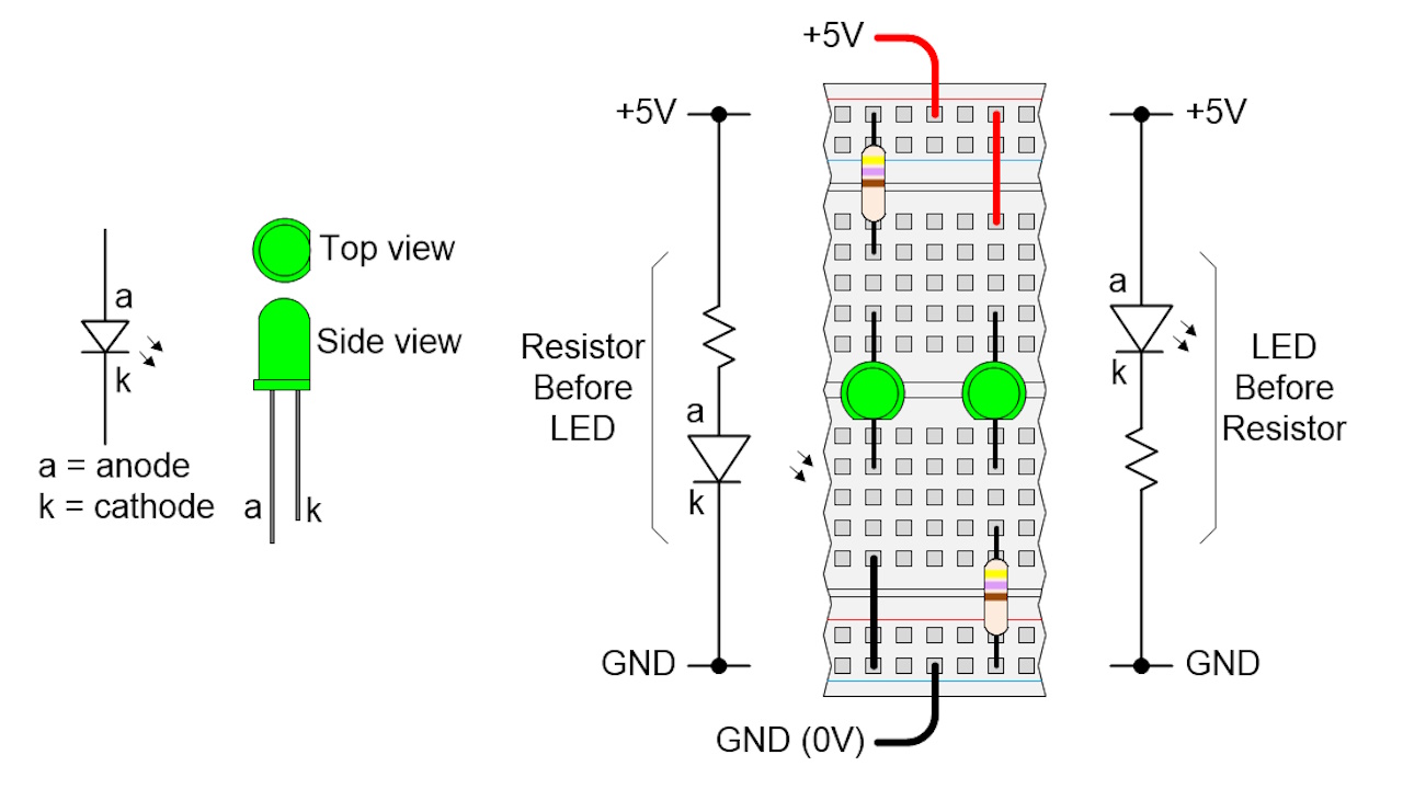
On the left is the schematic symbol for an LED and its physical appearance. On the right are two equivalent breadboard layouts for an LED circuit, with the resistor placed before and after the LED, demonstrating that order in a simple series circuit does not matter.
Follow these steps:
- Power the Breadboard: Connect the positive (+) lead of your 5V power supply to the red power rail on your breadboard. Connect the ground (GND) lead to the blue or black power rail.
- Place the LED: Insert the LED into the breadboard. Make sure its two legs are in different rows. A good practice is to have it straddle the central ravine. Remember the polarity: the longer leg (anode) should be on the side where the current will come from (the positive supply).
- Place the Resistor: Connect one leg of the 220Ω resistor to the same row as the LED's anode (the longer leg). Connect the other leg of the resistor to an empty row.
- Make the Connections:
- Use a jumper wire to connect from the red (+) power rail to the row containing the resistor leg that is not connected to the LED.
- Use another jumper wire to connect from the row containing the LED's cathode (the shorter leg) to the blue/black (–) ground rail.
Double-check your connections. The path should be:+5V Rail → Jumper Wire → Resistor → LED Anode → LED Cathode → Jumper Wire → GND Rail.
Once you are confident in your wiring, turn on your power supply. Your LED should light up!
The following video shows this process and also highlights common mistakes, which is a great way to learn how to debug your first hardware project.
This part of the Science Buddies video demonstrates building a simple LED circuit and discusses common errors.
Watch these two final sections: Building a Simple Circuit: See the flow of electricity through the breadboard in a working example. Common Mistakes: Learn to spot issues like incorrect connections, loose components, and reversed polarity.
Experiment and Observe
Now, try swapping the 220Ω resistor for a higher value, like a 1kΩ (1000Ω) resistor. What do you observe? The LED should be noticeably dimmer. This is because the higher resistance further limits the current flowing through the LED.

As shown here, increasing the resistance in series with an LED decreases the current, which in turn reduces the LED's brightness. The leftmost LED with the smallest resistor (150Ω) is the brightest.
This simple experiment provides tangible proof of the concepts we've discussed. You have successfully controlled the flow of electrons to produce a desired outcome.
Conclusion
Congratulations on building your first circuit! You have bridged the gap from an abstract schematic to a physical, glowing reality. This is a fundamental skill that underpins all practical work in electronics, robotics, and IoT.
Key Takeaways:
- A breadboard is a reusable tool for prototyping circuits by making temporary electrical connections.
- Holes in a breadboard's horizontal rows are connected, and the vertical power rails provide easy access to power and ground.
- An LED is a polarized component that requires a current-limiting resistor to prevent it from being destroyed by excessive current.
- The value of this resistor can be calculated with the formula .
- Building a circuit involves translating the logical connections of a schematic into physical connections on the breadboard, a process that requires careful attention to detail—your first exercise in hardware debugging.
You have now completed the first module of your electronics journey. In the next lesson, we will begin our study of DC Circuit Analysis. We'll start by formalizing the concept of components in series and parallel, building directly on the series circuit you just created, and learning how to analyze more complex networks.