Welcome to the second module of your electronics journey, where we'll move from single components to analyzing how they behave in networks. In the last lesson, you successfully built your first series circuit with an LED and a resistor. You learned that components connected in a single chain like that are "in series."
Today, we will formalize this concept and introduce its counterpart: the "parallel" connection. This lesson will equip you with the fundamental skill of calculating the total, or equivalent resistance, of resistor networks. Mastering this allows you to take a complex-looking circuit and simplify it into a single, predictable value, a crucial step for understanding the overall behavior of any electronic system you'll encounter in robotics and IoT.
Series vs. Parallel: The Two Fundamental Connections
In any circuit, components can be connected in one of two basic ways: series or parallel. The way they are connected determines how voltage and current are distributed among them.
- Series Connection: Components are connected end-to-end, creating a single path for the current to flow. Think of it as a one-lane road where all traffic must follow the same route. In the circuit you built, the power source, resistor, and LED were all in series.
- Parallel Connection: Components are connected across the same two points in a circuit, creating multiple paths for the current. Imagine a river splitting into several channels and then rejoining downstream; the water flow (current) divides among the channels.
The image below provides a great summary of how to identify these connections, what they look like in a schematic, and their key electrical properties.

This chart contrasts series and parallel resistor configurations, covering their identification, schematic appearance, shared electrical properties, and formulas for equivalent resistance.
To build a solid conceptual foundation, please watch the beginning of the following video, which uses the practical example of Christmas lights to illustrate the difference.
DC parallel circuits explained - The basics how parallel circuits work working principle
This video from The Engineering Mindset provides an excellent conceptual introduction to parallel circuits by contrasting them with the series circuits you're already familiar with.
Watch the first part of the video, from the beginning to the explanation of why parallel wiring is often preferred. Pay close attention to the idea of single versus multiple paths for the electrons.
For a more formal definition accompanied by hydraulic analogies—which can be very intuitive—the following text is highly recommended.
2.12 Resistors in Series & Parallel - Ultimate Electronics Book
This article from the Ultimate Electronics Book clearly defines series and parallel connections.
Please read the first two sections: Components in Series, which reinforces the idea of a single current path. Components in Parallel, which introduces the idea of current splitting across branches that share the same voltage.
Calculating Equivalent Resistance of Resistors in Series
As you now know, when resistors are connected in series, the current has to pass through each one sequentially. Each resistor adds its opposition to the flow. Therefore, the total resistance is simply the sum of the individual resistances.
The formula for the equivalent resistance ( or ) of resistors in series is:
Let's look at the formal derivation and a worked example. This process solidifies the relationship between Ohm's law, voltage drops, and series resistance.
Resistors in Series and Parallel | Physics
This chapter from Lumen Learning's Physics course provides a rigorous yet clear explanation of series circuits.
Read the section Resistors in Series. Focus on how the total voltage is the sum of the individual voltage drops, which directly leads to the formula for total resistance. Then, study Example 1, paying attention to how the total resistance is first used to find the total current, which is then used to find the voltage drop and power for each individual resistor.
Calculating Equivalent Resistance of Resistors in Parallel
When resistors are in parallel, the current splits. Adding another resistor in parallel opens up a new path, making it easier for current to flow. Consequently, the total equivalent resistance decreases.
Calculating parallel resistance is a little less direct. The formula is based on summing the conductance of each path, where conductance () is the reciprocal of resistance (). Total conductance is , which translates back to resistance as:
To find , you calculate the sum on the right and then take the reciprocal of the result. For the very common case of two resistors in parallel, this formula can be rearranged into a more direct form:
This is often called the "product over sum" rule and is a very handy shortcut.
The following video gives an excellent explanation for why we use this reciprocal formula, tying it back to the idea of conductance. This level of understanding is key to building a robust mental model.
DC parallel circuits explained - The basics how parallel circuits work working principle
This segment of the video from The Engineering Mindset demystifies the parallel resistance formula.
Please watch the section from "how do we calculate the total resistance in a parallel circuit?" up to the end of the explanation on conductance. This will clarify why the math works the way it does.
Now, let's see this formula applied in a detailed example.
Resistors in Series and Parallel | Physics
This section of the Lumen Learning article details the derivation for parallel resistance and provides a worked example.
Read the section Resistors in Parallel, including Example 2. Notice how the calculated equivalent resistance (0.804 Ω) is less than the smallest individual resistor (1.00 Ω). This is always true for parallel circuits and serves as a quick sanity check for your calculations.
Analyzing Combination (Series-Parallel) Circuits
Most real-world circuits aren't purely series or purely parallel; they are combinations of both. To analyze these, you apply a step-by-step reduction process. The strategy is to identify distinct groups of series or parallel resistors, calculate their single equivalent resistance, and then redraw the circuit with that simplified value. You repeat this until only one resistor remains.
This process is iterative and hierarchical, much like simplifying a complex mathematical expression or refactoring a block of code into a function. You find a discrete, analyzable unit, replace it with its simpler equivalent, and then re-evaluate the larger structure.
The image below illustrates this process perfectly. A complex network is reduced step-by-step into a simpler one.
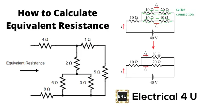
This diagram shows the step-by-step simplification of a combination series-parallel resistor network into a single equivalent resistance.
Let's walk through the methodology with a complete example.
Resistors in Series and Parallel | Physics
This final section of the article puts everything together, showing how to analyze a mixed circuit.
Read the section Combinations of Series and Parallel, including Example 3. Follow the logic carefully: first, the parallel combination of R2 and R3 is calculated. This result, R_p, is then treated as a single resistor in series with R1.
To see this technique applied to a variety of problems, the following video is an excellent resource. You can watch as many examples as you feel you need to become comfortable with the pattern.
Resistors In Series and Parallel Circuits - Keeping It Simple!
This video from The Organic Chemistry Tutor is a great problem-solving session that works through numerous examples of increasing complexity.
Watching the section on combination circuits will help you solidify the step-by-step reduction method. Try to pause the video before each new problem and solve it yourself, then watch the solution.
Practice Your Skills
Let's test your understanding. Using the formulas and techniques from this lesson, solve the following problems. You can find these in the "Problems & Exercises" section of the Lumen Learning article.
- What are the largest and smallest resistances you can obtain by connecting a 36.0-Ω, a 50.0-Ω, and a 700-Ω resistor together? (Problem #3)
- Given a 48.0-V battery and 24.0-Ω and 96.0-Ω resistors, find the current and power for each when connected in series. (Problem #6a)
- Repeat the previous problem, but this time with the resistors connected in parallel. (Problem #6b)
Think about how you would connect the resistors to achieve the largest and smallest total resistance before you start calculating.
Conclusion
In this lesson, you've moved beyond simple circuits to analyzing networks. You now have the analytical tools to simplify complex resistor arrangements into a single equivalent value, a foundational skill for all circuit analysis.
Key Takeaways:
- Series circuits provide a single path for current. The current is constant through all components, and the total resistance is the sum of individual resistances:
- Parallel circuits provide multiple paths for current. The voltage is constant across all branches, and the total resistance is found using the reciprocal formula: . The equivalent resistance is always less than the smallest individual resistance in the parallel network.
- Combination circuits are solved by iteratively identifying series or parallel sub-networks, calculating their equivalent resistance, and redrawing the simplified circuit until only one resistor remains.
This skill of circuit reduction is powerful, but it has its limits. Some circuits, like bridge networks, cannot be simplified using these rules alone. In our next lesson, we will introduce Kirchhoff's Voltage Law (KVL), a more universal tool that allows us to analyze any circuit loop by stating that the sum of all voltage drops and rises in a closed loop must equal zero.