Introduction
In our last lesson, you learned how to design and apply Access Control Lists (ACLs) to filter traffic between VLANs. ACLs are a powerful tool for implementing security policies on a network where, by default, all routed segments can communicate with each other. You learned to permit and deny specific traffic flows based on source, destination, and port numbers.
Today, we take the concept of network segmentation a step further. While ACLs filter traffic, Virtual Routing and Forwarding (VRF) provides complete isolation. This lesson directly addresses a key part of your goal: implementing robust separation for different types of traffic, such as isolating corporate data from guest internet access.
We will cover what VRFs are, why they are a cornerstone of modern network design, and how to integrate a VRF-based design into your architecture. By the end of this lesson, you will be able to design a two-VRF topology that meets specific traffic separation requirements, a crucial skill for building secure, scalable networks.
1. What is a VRF? From Virtual Switches to Virtual Routers
You're already very familiar with VLANs. A helpful way to think about VRFs is by analogy:
- VLANs do for Layer 2 what VRFs do for Layer 3.
VLANs create separate Layer 2 broadcast domains, effectively turning one physical switch into multiple virtual switches. However, once you add a Layer 3 gateway (like an SVI on an L3 switch), traffic can be routed between those VLANs.
VRFs solve this by creating multiple, independent routing tables on a single physical router or L3 switch. Each VRF has its own set of interfaces, its own routing table, and its own forwarding table (FIB). Traffic in one VRF is completely invisible to and isolated from traffic in another VRF by default. It's like having multiple virtual routers living inside one physical box.
This video from Network Direction provides an excellent conceptual introduction.
How VRFs Work (VRF Lite) | VRFs Part 1
Let's start with a clear conceptual overview of what VRFs are and the problem they solve. This video provides a great analogy and demonstration.
Watch the first 2 minutes and 14 seconds. Focus on the comparison between VLANs (Layer 2 separation) and VRFs (Layer 3 separation), and the concept of a router having multiple, independent routing tables instead of just one 'global' table.
The key takeaways are:
- A standard router has a single global routing table. All routes from all interfaces go into this one table.
- A VRF-enabled router has multiple tables: the global one plus one for each VRF you create.
- Interfaces (or SVIs) are assigned to a specific VRF, and their routes populate that VRF's table only.
This fundamental isolation is what makes VRFs so powerful for security and multi-tenant architectures.
2. Designing a Two-VRF Topology for Traffic Separation
Your requirement to separate corporate traffic from guest/internet traffic is a classic use case for VRF-Lite (the most common implementation of VRFs in an enterprise campus network). Let's design a simple, effective topology to achieve this.
The Goal:
- All internal, trusted traffic (Staff, Servers, Finance, etc.) must be able to communicate with each other, governed by the ACLs we designed in the last lesson.
- All guest traffic must be completely isolated from the internal network.
- Guest traffic should only be able to access the internet.
The Design:
We will create two VRFs on our Layer 3 switch:
CORP: This VRF will contain all the SVIs for our internal VLANs. This will be the "trusted" virtual router.GUEST: This VRF will contain the SVI for the Guest Wi-Fi VLAN. This will be the "untrusted" virtual router.
By default, the L3 switch will not forward packets between the CORP and GUEST VRFs. They are in separate universes.
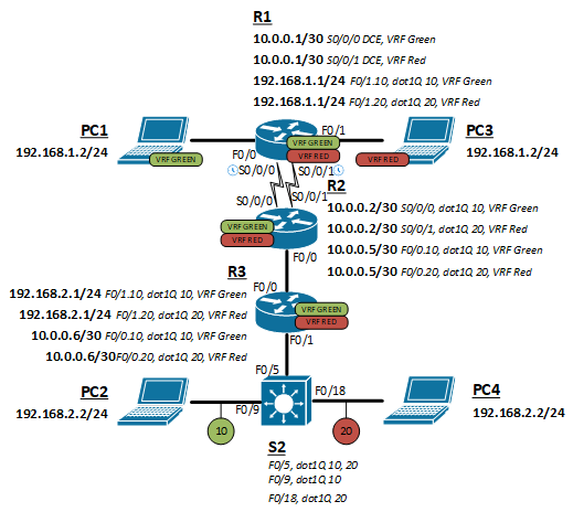
Now, let's review the mechanics of VRF-Lite and how interfaces are managed. Since you have experience with Allied Telesis, their documentation provides a good, vendor-neutral explanation of the core concepts.
[PDF] VRF-lite on Switches Feature Overview and Configuration Guide
This feature guide from Allied Telesis explains the fundamentals of VRF-lite. The concepts are universal, and we'll map them directly to the Cisco commands you're used to.
Read the sections 'What is VRF-lite?' (page 4) and 'Understanding VRF-lite' (pages 6-8). Focus on: The purpose: isolating networks and allowing IP address reuse. The concept of VRF security domains and independent routing tables. How interfaces are managed. Note the important detail that an interface's IP configuration is removed when you move it into a VRF.
3. Basic VRF Configuration and Verification
Let's translate this design into the basic Cisco IOS commands. The process is straightforward:
- Define the VRF instance.
- Assign an interface (or SVI) to the VRF.
- Re-configure the IP address on the interface.
- Verify the isolation.
! Enter global configuration mode
conf t

! Step 1: Define the VRFs
ip vrf CORP
 description For all internal trusted traffic
!
ip vrf GUEST
 description For untrusted guest and internet-only traffic

! Step 2: Assign an SVI to a VRF
! Let's assume VLAN 110 is for Corporate IT staff
interface Vlan110
 ! First, we must remove the IP address
 no ip address
 ! Now, assign the SVI to the VRF
 ip vrf forwarding CORP

! Step 3: Re-configure the IP address
 ip address 10.10.0.1 255.255.255.0

! Repeat for the Guest VLAN (e.g., VLAN 666)
interface Vlan666
 no ip address
 ip vrf forwarding GUEST
 ip address 172.16.66.1 255.255.255.0

end
Once configured, you can verify the separation using show commands.
show ip routewill now only show routes in the global routing table (which should be mostly empty of our VLANs).show ip route vrf CORPwill show only the routes associated with theCORPVRF (e.g., the10.10.0.0/24network).show ip route vrf GUESTwill show only the routes for theGUESTVRF.
To perform diagnostics like ping or traceroute from the perspective of a specific VRF, you must specify it in the command:ping vrf GUEST 8.8.8.8
This video demonstrates the configuration process and the verification steps, including the important "gotcha" about IP addresses being removed.
How VRFs Work (VRF Lite) | VRFs Part 1
Now, let's watch the configuration in action. This part of the 'How VRFs Work' video shows the CLI commands for creating VRFs, assigning interfaces, and verifying the isolated routing tables.
Watch from 02:14 to 07:59. Pay close attention to: The ip vrf <name> command to create the VRF. The ip vrf forwarding <name> command on the interface. The fact that the IP address must be re-applied after moving the interface. The use of ping vrf <name> and show ip route vrf <name> to work within the context of a specific VRF.
4. Enabling Shared Services: Inter-VRF Routing
We've successfully isolated the CORP and GUEST networks. But now we have a new problem: how does the GUEST VRF get to the internet? The physical internet connection (e.g., to a firewall or ISP router) will likely exist in one place, but both VRFs need to use it.
We cannot have hosts in the GUEST VRF communicating with hosts in the CORP VRF, but they both need to reach a shared resource (the internet gateway). This is achieved through inter-VRF routing, also known as "route leaking." We will selectively leak only the routes necessary for internet access, without compromising the isolation between our two main VRFs.
For your specific goal, the most direct approach is to create a third VRF for shared services.
The refined design:
CORPVRF: Contains all internal SVIs.GUESTVRF: Contains the guest SVI.INTERNETVRF: A new VRF that contains the physical interface or SVI connecting to your network edge (e.g., firewall).
We then configure specific static routes to leak the default route (0.0.0.0/0) from the INTERNET VRF into the CORP and GUEST VRFs.

The Allied Telesis guide provides an excellent explanation of this exact scenario.
[PDF] VRF-lite on Switches Feature Overview and Configuration Guide
Let's return to the Allied Telesis guide to understand how to provide shared services like internet access to multiple isolated VRFs.
Read the sections 'Inter-VRF communication' (page 9) and 'How VRF-lite security is maintained' (page 24). Focus on the diagram and explanation of using a 'shared VRF' for internet access. The key security point on page 24 is critical: by default, you cannot use the shared VRF as a 'bridge' to get from one client VRF to another. This is the mechanism that keeps your GUEST and CORP traffic separate even while they share an internet connection.
The simplest way to leak the internet route is with a VRF-aware static route. If your internet gateway is 198.51.100.1, reachable via the INTERNET VRF, you would add these static routes to the CORP and GUEST routing tables:
! Add a default route to the CORP VRF pointing to the internet gateway
ip route vrf CORP 0.0.0.0 0.0.0.0 198.51.100.1

! Add the same default route to the GUEST VRF
ip route vrf GUEST 0.0.0.0 0.0.0.0 198.51.100.1
This configuration ensures that any traffic from the CORP or GUEST networks that doesn't have a more specific route will be forwarded to the internet gateway. Crucially, the VRFs themselves remain isolated from each other.
Conclusion
You have now integrated a core virtualization technology into your network design. You've moved beyond simple filtering with ACLs to creating fundamentally isolated routing domains with VRFs. This is a massive leap in security and network architecture flexibility.
Key Takeaways:
- VRFs create virtual routers within a single physical device, each with its own independent routing table.
- The primary use case in the enterprise is to isolate traffic with different security requirements, such as separating trusted corporate users from untrusted guests.
- A common and effective design pattern is the two-VRF model (
CORPandGUEST), often supplemented with a thirdINTERNETVRF for shared services. - Assigning an SVI to a VRF is a simple process, but you must remember to re-apply the IP configuration.
- Inter-VRF routing ("route leaking") is necessary to allow isolated VRFs to access shared resources like an internet connection. This can be done selectively with static routes to maintain security.
Preview of the Next Lesson:
Our design is nearly complete. We have a segmented VLAN plan, a secure addressing scheme with VLSM, inter-VLAN filtering with ACLs, and now macro-segmentation with VRFs. The final step in this module is to ensure our routing is efficient. In the next lesson, we will focus on Route Summarization. You'll learn how to aggregate multiple specific subnet routes into a single summary route, which reduces the size and complexity of your routing tables and improves network stability.