Introduction
Welcome to the final lesson of your capstone project module. Over the last several lessons, you've moved step-by-step through the process of designing a large-scale network. You've translated business needs into technical requirements, developed a VLAN and VLSM plan, defined the Layer 3 routing topology, secured it with ACLs, and created traffic isolation using VRFs. You now have all the individual components of a comprehensive network architecture.
Today's lesson is about bringing it all together. The goal is to compile all these design artifacts into a single, professional final project document. A collection of diagrams and spreadsheets is useful, but a formal design document is what turns a plan into a professional blueprint for implementation, troubleshooting, and future growth. This is the deliverable that proves the design and communicates its value to your team and stakeholders.
1. The Anatomy of a Professional Network Design Document
Before you start compiling, it's important to understand what makes a good design document. It's not just a data dump; it's a structured narrative that explains what you designed and, more importantly, why you made those choices. It serves several audiences:
- Fellow Engineers: Need it for implementation and day-to-day operations.
- Management: Needs to understand the high-level design and how it meets business goals.
- Your Future Self: Will thank you for it six months from now when you need to remember a specific detail.
The best way to understand this is to see an example. The following document is a sample Network Design Report. While it focuses on OSPF and specific hardware, its structure is an excellent model for what you will create.
[PDF] Network Design Report - RouteHub
Let's examine the structure of a professional Network Design Report from RouteHub. This will serve as a template for your own capstone document.
Read pages 4 through 7 of the PDF. Pay close attention to the document's structure: Introduction (Page 4): Notice how it starts by stating the business and technical requirements the design aims to solve. Network Design (Page 5): This section presents a high-level overview and a topology diagram (though the diagram itself is just a placeholder here, the concept is key). Network Frameworks (Pages 6-7): Here, it breaks down the design into logical components, like the Local Area Network (LAN), and explains the design choices (e.g., two-tier hierarchy, oversubscription, hardware choices).
As you can see, the document flows logically from the high-level requirements down to the specific design details, explaining the rationale at each step.
2. Best Practices for Your Design Artifacts
Your final document will synthesize several key artifacts. Let's ensure each one is clear, informative, and professional. The PacketPushers article on documentation best practices offers some great, no-nonsense advice for working engineers.
Network Documentation Best Practices: What's Important & How To ...
This article from PacketPushers provides practical tips on creating documentation that is actually useful. We'll focus on the sections relevant to your project artifacts.
Read the sections 'L1/L2 drawings', 'L3 drawings', and 'IP addresses'. Focus on these key takeaways: For Drawings: Simplicity and information density are more important than 'pretty' icons. Include hostnames, management IPs, and interface labels. A drawing should be a tool, not a marketing slide. For IP Addresses: 'Pinging to find a free IP is not acceptable.' Your IPAM document is the single source of truth for all subnets, static assignments, and DHCP scopes.
Let's break down how to apply this to your main artifacts.
2.1. The Topology Diagram: Your Master Blueprint
This is the centerpiece of your design document. It should provide a visual summary of the entire architecture. A good diagram allows someone to understand the network's structure at a glance.
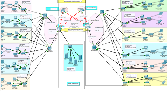
When creating your diagram, remember the advice from PacketPushers: focus on clarity. Include:
- Switches, routers, and firewalls.
- Connections between devices, including port-channels.
- VLANs and their associated subnets.
- VRF boundaries.
- Key IP addresses, like SVIs (gateways).
2.2. Data Tables: VLANs, IPAM, and ACLs
While the diagram provides the visual overview, the detailed data is best presented in tables.
- VLAN Plan: A simple table listing VLAN ID, VLAN Name, a brief description of its purpose (e.g., "Staff - Marketing Dept"), and the IP subnet assigned to it.
- IPAM Document: This is the master spreadsheet you developed. It contains the full breakdown of your VLSM plan, including network address, prefix, usable range, and broadcast for every subnet. You can either embed a summary table in your main document or include the full spreadsheet as an appendix.
- ACL Policy: Don't just paste CLI code. Create a table that translates the policy into plain English. This is crucial for security audits and troubleshooting.
Here's a good format for your ACL policy table:
| Rule # | Source VLAN/Subnet | Destination VLAN/Subnet | Protocol/Port | Action | Justification |
|---|---|---|---|---|---|
| 10 | Staff (10.1.10.0/24) | Servers (10.1.100.0/24) | TCP/443 (HTTPS) | Permit | Allow staff to access the internal web server. |
| 20 | Staff (10.1.10.0/24) | Finance (10.1.20.0/24) | Any | Deny | Isolate Finance department from general staff. |
| ... | ... | ... | ... | ... | ... |
3. Your Capstone Task: Compile the Final Design Document
It's time to assemble your work. Your task is to create a single, cohesive document that incorporates all the design artifacts you've built throughout this module. Treat this as a formal deliverable you would hand over to a client or your boss.
Instructions:
Create a document (e.g., in PDF or Word format) that follows the structure below. Use the requirements defined in the first lesson of this module as the basis for your design.
Network Design Document
1.0 Introduction
- 1.1 Project Overview: Briefly state the purpose of the project.
- 1.2 Business & Technical Requirements: Summarize the key requirements that drove your design (e.g., number of users, security needs, traffic isolation).
2.0 High-Level Network Topology
- Insert your master network topology diagram here. It should be legible and detailed enough to show the overall architecture, including VLANs, key subnets, and VRF boundaries.
3.0 Logical Network Design
- 3.1 VLAN Architecture:
- Provide a brief narrative explaining your VLAN segmentation strategy (e.g., by department, function).
- Include your VLAN Plan table (VLAN ID, Name, Description, Subnet).
- 3.2 IP Addressing Plan (VLSM & IPAM):
- Explain the parent address block you were assigned and how you used VLSM to create subnets.
- Provide a summary of your IP Address Management (IPAM) plan. You can reference your full IPAM spreadsheet as an appendix.
- 3.3 Layer 3 Routing Design:
- Describe where the Layer 3 routing occurs (e.g., on a core L3 switch).
- Explain your SVI placement and addressing strategy (e.g., using the first usable IP of each subnet for the gateway).
- Describe your VRF design, explaining which VLANs/SVIs belong to which VRF (
CORP,GUEST, etc.) and how you are providing internet access to each.
4.0 Network Security Policy
- 4.1 Inter-VLAN Access Control:
- Explain your overall security philosophy (e.g., default deny between most VLANs, with specific exceptions).
- Include your detailed ACL Policy table (as shown in the example above).
- State where the ACLs will be applied (e.g., "inbound on SVI 10").
Appendix A: Full IPAM Spreadsheet
- (Optional but recommended) Attach or link to your complete IPAM document.
Conclusion
Congratulations on reaching the final stage of the capstone project. By compiling these artifacts into a formal document, you are demonstrating a crucial skill that separates a technician from an architect. A well-documented design is scalable, maintainable, and defensible. It is the final and most critical piece of any network engineering project.
Key Takeaways:
- A design document tells the story of your network, explaining the what and the why.
- Structure is key: A logical flow from requirements to high-level design to detailed components makes the document easy to understand and use.
- Clarity over aesthetics: Your diagrams and tables should be information-rich tools, not works of art.
- Documentation is not an afterthought; it is an integral part of the design process.
Preview of the Next Module:
Now that you have successfully designed a complete network architecture from scratch, we will shift your focus from creation to analysis. In the next module, Architecture Analysis and Critique, you will learn how to evaluate existing network designs. You'll apply your knowledge to identify inefficiencies in addressing, find security gaps in VLAN and ACL implementations, and assess the overall scalability of a given architecture. This will sharpen your critical thinking and elevate your ability to act as a senior design resource.