Introduction
Welcome to the first lesson of our final module, "Architecture Analysis and Critique." In the previous module, you successfully completed a capstone project where you designed a complex network from the ground up. You translated requirements into a full-fledged architecture, complete with a VLAN plan, a VLSM addressing scheme, L3 routing, and security policies using ACLs and VRFs. In short, you've learned how to create a network blueprint.
Now, we shift our focus from creation to analysis. In the real world, you'll more often inherit, troubleshoot, or expand an existing network than you will build one from a blank slate. Being able to quickly understand and evaluate an existing design is a critical skill that distinguishes a senior engineer.
In this lesson, you will analyze a sample network design's documentation to identify its IP addressing scheme, VLAN structure, and security policies. This is the first step in network critique: before you can judge if a design is good, you must first understand what the design is.
1. The Three Pillars of Network Design Analysis
When you're handed a piece of network documentation—be it a diagram, a spreadsheet, or a formal report—you are essentially looking for the answers to three fundamental questions. These are the pillars of the network's architecture:
- IP Addressing Scheme: How is the network logically organized and addressed? This is the network's map.
- VLAN Structure: How is the network segmented at Layer 2? This defines the broadcast domains and the initial lines of traffic separation.
- Security Policies: What are the rules of communication between different parts of the network? This is often implied by the segmentation and addressing choices.
Your task as an analyst is to reverse-engineer the designer's intent by examining how they constructed these three pillars.
2. Case Study: Deconstructing an Enterprise Network
The best way to learn analysis is to practice on a realistic example. We will use a detailed case study of a fictional company, "Cisco Jedi, LLC," to practice this skill. The article presents a complete design and explains the rationale behind it, making it an excellent learning tool.
First, let's get acquainted with the scenario.
Designing a Scalable Enterprise IP Scheme
Let's begin our analysis with this comprehensive case study from the 'Cisco Jedi' blog. It walks through a complete enterprise IP scheme. We will use this as our primary example to dissect.
Read the section 'CASE STUDY – CISCO JEDI, LLC'. This will give you the necessary context on the company's structure, locations, and network topology, which is crucial for understanding the design choices that follow.
3. Pillar 1: Analyzing the IP Addressing Scheme
With the context of the company in mind, let's dissect the first and most critical pillar: the IP addressing scheme. A well-planned scheme provides structure, simplifies routing, and makes the network predictable. The goal is to be able to look at any IP address and know its location and purpose.
Designing a Scalable Enterprise IP Scheme
Now, let's analyze the high-level IP plan. A good scheme is hierarchical and allows for easy summarization.
Read the section 'GLOBAL ADDRESSING SCHEME'. As you read, find the answers to these questions: What is the parent address block chosen for the entire enterprise (e.g., 10.0.0.0/8, 172.16.0.0/12)? What format is used to assign Site IDs? How can you tell if an IP address belongs to the New York branch versus the Los Angeles Data Center? What specific strategy is used to address the 400+ retail stores in a scalable way? How is Store #222 addressed?
From your reading, you should have identified a clear, hierarchical structure:
- The entire enterprise uses the
10.0.0.0/8block for its private, routable network. - The scheme follows a
10.site_id.subnet.hostformat. - The second octet identifies the physical site or a group of sites. For example, any address starting with
10.14.x.xis in New York. - The retail stores use a clever two-octet system (
10.10X.store_#) to accommodate thousands of locations while keeping the addresses contiguous for easy summarization. For example, Store 222 is in the10.102.22.x/24subnet.
This type of planning is the hallmark of a scalable design.
4. Pillar 2: Analyzing VLAN and Subnet Structure
Now let's drill down into how this IP plan is mapped to the Layer 2 segmentation. In any modern network, there is a tight, 1:1 relationship between a VLAN and an IP subnet. Analyzing the VLAN plan reveals how the network is segmented by function, department, or traffic type.
Let's start with a visual example of how this is often documented.
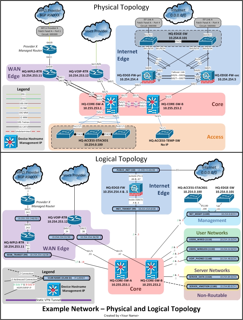
Now, let's return to our case study to see how the Cisco Jedi design documents this.
Designing a Scalable Enterprise IP Scheme
With the high-level IP plan understood, let's examine the VLAN structure. This is where you'll see how the network is segmented by function.
Study the tables under 'LOS ANGELES CORPORATE VLANS', 'DATACENTER VLANS', and 'BRANCH VLANS', as well as the subnetting template for the retail stores under 'A NOTE ON EFFICIENCY'. Focus on: VLAN Function: How are VLANs categorized? (e.g., by user type, traffic type, security need). VLAN-to-Subnet Mapping: What is the relationship between the VLAN number and the IP subnet? (Hint: compare the VLAN number to the third octet). Subnet Sizing: Note the different prefix lengths (/22, /24, /26) used for different VLANs. For now, just identify them; we will critique the efficiency in our next lesson.
This analysis reveals another powerful design pattern. The scheme consistently uses the third octet of the IP subnet to match the VLAN ID. For example:
- VLAN 32 (Voice) is assigned the network
10.##.32.0/22. - VLAN 100 (Servers) is assigned the network
10.##.100.0/22.
This makes the network highly predictable and "self-documenting." If you see an alert for an IP address like 10.10.32.50, you can instantly deduce it's a Voice device at the Los Angeles corporate site. This consistency is invaluable for operations and troubleshooting.
5. Pillar 3: Inferring Security Policies
The final pillar is security. While a design document may not list every line of an ACL, the addressing and segmentation choices create an implicit security policy. By separating traffic into different VLANs and subnets, the designer is creating control points for a firewall or Layer 3 switch to enforce rules.
A great example of this is the handling of guest or untrusted traffic. Let's watch a short clip where network expert Jeremy Cioara explains the thought process behind isolating "Bring Your Own Device" (BYOD) traffic.
DESIGNING Subnets for Your Company!
Watch this clip to understand how addressing choices can enforce a security policy, specifically for guest or BYOD networks.
Watch the video from 06:30 to 07:35. Pay attention to why a different IP address range (172.16.0.0/22) is used for the guest network (VLAN 30) instead of the corporate 10.x.x.x range.
As the video explains, using a completely separate address space (172.16.x.x) for guest traffic that will only go to the internet makes it very simple to create high-level security rules. You can create a rule that says "no traffic from 172.16.0.0/12 is ever allowed to talk to 10.0.0.0/8." This is a security policy enforced through addressing.
Now, let's look for similar policy implications in our Cisco Jedi case study.
Designing a Scalable Enterprise IP Scheme
Let's apply this concept to our case study. Look for addressing choices that imply a security boundary.
Read the brief sections on 'DMZ' and 'MPLS/BGP CORE'. Ask yourself: What IP range is used for the public-facing DMZ? Why is it different from the main 10.x.x.x corporate network? The design separates Voice, Finance, and Standard Users into different VLANs. What does this separation imply about the intended security policy?
By analyzing the design, you can infer several security policies:
- DMZ Isolation: The DMZ uses the
172.22.x.xrange, completely separate from the internal10.x.x.xnetwork. The implicit policy is that traffic from the internet hits the DMZ, and strict firewall rules will control any communication between172.22.x.xand10.x.x.x. - Departmental Segmentation: The creation of separate VLANs for Finance (VLAN 24), Design (VLAN 16), and Standard Users (VLAN 8) implies a policy of least privilege. The intent is to use ACLs to prevent these groups from accessing each other's resources unless specifically permitted.
- Traffic Type Segmentation: Separating Voice (VLAN 32) and Management (VLAN 200) traffic allows for both security and QoS policies to be applied easily. Access to the management network can be heavily restricted, and voice traffic can be prioritized over data.
Conclusion
In this lesson, you took the first step into network architecture analysis. You've learned to deconstruct a professional design document by focusing on the three pillars: the IP addressing scheme, the VLAN structure, and the implicit security policies. By systematically examining these elements, you can quickly understand the layout, organization, and intent of even a large, complex network.
Key Takeaways:
- Analyzing a network design involves reverse-engineering the designer's intent.
- Hierarchical addressing schemes (e.g.,
10.site.vlan.host) make a network scalable, predictable, and easier to manage. - The 1:1 mapping between VLANs and subnets is the foundation of modern network segmentation. Patterns like matching the VLAN ID to a subnet octet are common best practices.
- Addressing and segmentation choices create an implicit security policy by establishing control points and clear boundaries between different types of traffic.
Preview of the Next Lesson:
Now that you can identify what a design is, the next logical step is to ask, "Is this design any good?" In the next lesson, you will learn to critique the efficiency of a given address allocation plan using VLSM principles and calculate potential address savings. We will move from identification to evaluation.