Introduction
In our last lesson, you learned how to deconstruct a network design by analyzing its three core pillars: the IP addressing scheme, the VLAN structure, and the implicit security policies. You practiced this by examining the "Cisco Jedi" case study, learning to read the blueprint of a complex network and understand the designer's intent.
Today, we move from identification to evaluation. It's not enough to understand what a design is; a senior engineer must be able to judge if it's a good design. This lesson directly addresses your goal of minimizing IP address waste. We will focus on critiquing the efficiency of an addressing plan, a crucial skill for optimizing and scaling any network architecture.
Our learning outcome is to critique the efficiency of a given address allocation plan using VLSM principles and calculate potential address savings. You will learn to spot waste, quantify it, and understand the methods for creating more efficient, "right-sized" allocations.
1. The Core Problem: Wasted Address Space
The fundamental goal of an efficient IP plan is to allocate just enough addresses for a given network segment's current and future needs, without being wasteful. Using subnets that are too large is a common mistake, especially in legacy designs.
A classic example is using a large subnet for a simple point-to-point link between two routers.
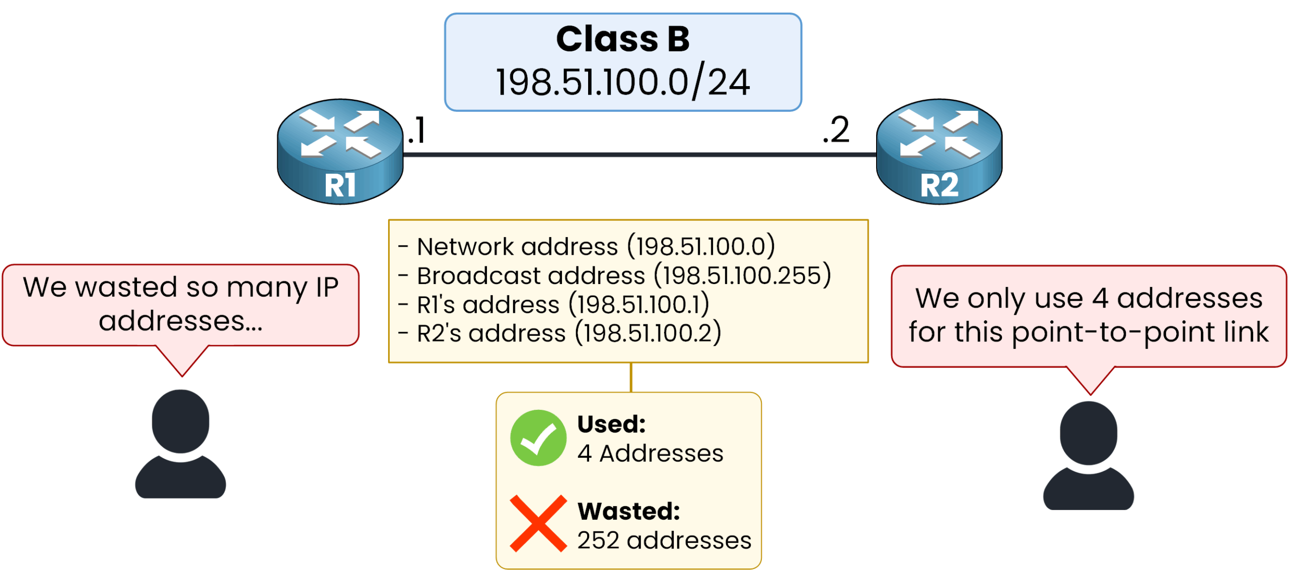
This problem arises from using a Fixed-Length Subnet Mask (FLSM), where every subnet in a network is the same size. The solution is Variable-Length Subnet Masking (VLSM), which allows you to use different subnet mask sizes for different segments within the same parent network. This lets you "right-size" each subnet.
Let's read a formal definition to solidify this concept.
This PDF from the Cisco Community provides a clear definition of VLSM and its primary benefit. It sets the stage for why this technique is essential for efficient design.
Read the introductory section 'VLSM Concepts and Configuration' (pages 530-531). Focus on the definition of VLSM and the explanation of its main benefit: reducing the number of wasted IP addresses.
2. Case Study: Critiquing an Inefficient Plan
Now let's apply this concept to the "Cisco Jedi" case study you analyzed previously. The article provides a perfect "before and after" scenario for critiquing efficiency.
Designing a Scalable Enterprise IP Scheme
Let's revisit the 'Cisco Jedi' article. The author presents an inefficient plan proposed by an employee and then contrasts it with a much more efficient VLSM-based solution. This is a perfect real-world example of the critique process.
Read the section 'COMPREHENDING THE BATTLE PLAN', focusing specifically on the subsection titled 'A NOTE ON EFFICIENCY'. First, analyze the inefficient plan, then study the proposed efficient solution.
Let's break down the critique and calculate the potential savings.
The Inefficient Plan:
- Allocation: Each retail store is given two separate
/24subnets (one for data, one for voice). - Total Addresses Allocated per Store: A
/24subnet has 256 total addresses (254 usable). So,2 * 256 = 512addresses are allocated to each store.
The Efficient VLSM Plan:
- Allocation: Each store is given a single
/24subnet, which is then subdivided using VLSM into four/26subnets for different functions (POS, Wireless, VoIP, Corporate). - Total Addresses Allocated per Store: A single
/24means only256total addresses are allocated. - Breakdown: Each
/26subnet provides 64 addresses (62 usable), which is a much more reasonable size for these specific functions in a small retail store.
Calculating the Savings:
By switching from the inefficient plan to the efficient VLSM plan, the company saves:
512 addresses (inefficient) - 256 addresses (efficient) = 256 addresses saved PER STORE
Now, let's scale that across the entire retail network of 400 stores:
256 addresses/store * 400 stores = 102,400 addresses
This is a massive saving. The inefficient plan would have wasted over 100,000 IP addresses, potentially forcing the company to re-architect its entire IP scheme as it expands. This calculation demonstrates the profound impact of efficient VLSM design.
3. The Mechanics of Efficient VLSM Allocation
To design or critique effectively, you must understand the correct procedure for VLSM allocation. A key principle is to allocate subnets from largest to smallest. This prevents smaller subnets from getting "stranded" in address space that could have been used for a larger block, a problem known as fragmentation.
This video provides an excellent visual demonstration of this process.
Variable-Length Subnet Mask (VLSM) - Subnetting Mastery - FLSM and VLSM Appendix Part 2 of 2
This video from Practical Networking clearly illustrates the two-step process for solving VLSM problems, emphasizing the 'largest to smallest' rule.
Watch from 05:18 to 08:16. The presenter explains the two overarching steps: 1) list all required subnet sizes, and 2) allocate from largest to smallest. Pay close attention to how this method avoids leaving 'orphaned' blocks of IP addresses.
4. A Critical Flaw: Detecting Overlapping Subnets
An address plan can seem efficient on the surface, but if its subnets overlap, it is fundamentally broken. Overlapping subnets mean that two different parts of your network are assigned the same range of IP addresses, which leads to routing failures and unpredictable connectivity issues. A critical part of any design critique is verifying that no overlaps exist.
There is a systematic process for finding these overlaps.
Now for a crucial skill in critiquing any IP plan: finding overlaps. This section of the Cisco PDF provides a methodical, three-step process to identify if any subnets in a VLSM design conflict with each other.
Read the section 'Finding VLSM Overlaps' (pages 532-536). You don't need to do the 'Practice Finding VLSM Overlaps' problems yet. Focus on understanding the three-step process described: Calculate the subnet ID and broadcast address for each subnet. List the subnets in numerical order. Scan the list to see if any address ranges overlap.
Practice: Find the Overlap
Let's apply this process. Imagine you are given a network design document with the following subnets. Is this design valid?
172.16.126.151/22172.16.122.57/27172.16.122.33/30172.16.122.1/30172.16.128.151/20
Follow the three-step process you just read about. Calculate the network and broadcast address for each, sort them, and check for overlaps.
Click here to see the step-by-step solution.
Step 1 & 2: Calculate Ranges and Sort
First, we find the subnet ID and broadcast address for each entry and list them in numerical order.
| Original Address & Mask | Subnet ID | Broadcast Address |
|---|---|---|
172.16.122.1/30 |
172.16.122.0 |
172.16.122.3 |
172.16.122.57/27 |
172.16.122.32 |
172.16.122.63 |
172.16.122.33/30 |
172.16.122.32 |
172.16.122.35 |
172.16.126.151/22 |
172.16.124.0 |
172.16.127.255 |
172.16.128.151/20 |
172.16.128.0 |
172.16.143.255 |
Step 3: Scan for Overlaps
Looking at the sorted list, we can immediately see a problem.
- The subnet
172.16.122.32/27covers the range from.32to.63. - The subnet
172.16.122.32/30covers the range from.32to.35.
The range of the /30 subnet is completely contained within the range of the /27 subnet. This is an invalid, overlapping design. The addresses 172.16.122.33 and 172.16.122.34 exist in two different subnets simultaneously, which would break routing.
5. Quantifying Efficiency: Address Utilization
The final step in our critique is to put a number on efficiency. We can do this by calculating the address utilization percentage. This metric tells you what percentage of the allocated addresses are actually being used (or are planned for use).
The formula is straightforward:
A good design aims for reasonable utilization while still leaving room for growth. Very low utilization (like < 20%) is a red flag for a wasteful allocation.
Let's apply this to our "Cisco Jedi" retail store example. Assume a store requires a total of 100 host addresses across all its functions.
-
Inefficient Plan Utilization:
- Required Hosts: 100
- Allocated Usable Hosts: 508 (from two /24 subnets: 254 + 254)
- Utilization = (
100 / 508) * 100 ≈ 19.7%
-
Efficient Plan Utilization:
- Required Hosts: 100
- Allocated Usable Hosts: 248 (from four /26 subnets: 4 * 62)
- Utilization = (
100 / 248) * 100 ≈ 40.3%
The calculation confirms our critique: the VLSM plan is more than twice as efficient in its address utilization for the same requirement. Professional IP Address Management (IPAM) documents, like the one shown in the "Addressing Plan Template" image, often track these metrics, including columns for immediate and projected future needs to ensure the allocated space is sufficient over time.
Conclusion
In this lesson, you graduated from simply identifying a network's design to critically evaluating its efficiency. You've learned that a good addressing plan is not just about connectivity; it's about the responsible and scalable management of a finite resource.
Key Takeaways:
- Critiquing efficiency involves comparing the number of required hosts against the number of allocated addresses in a subnet.
- VLSM is the primary technique for "right-sizing" subnets to match requirements and minimize IP address waste.
- The "largest-to-smallest" allocation method is a best practice that prevents address space fragmentation.
- An efficient design must be free of overlapping subnets. You learned a systematic process to detect these critical flaws.
- Address Utilization % is a key metric used to quantify the efficiency of an allocation plan.
Preview of the Next Lesson:
You have now analyzed a design's structure and critiqued its efficiency. The next layer of analysis involves security. In our next lesson, you will learn to identify security gaps or inefficiencies in a sample architecture's VLAN and ACL implementation. We will look for common vulnerabilities and design weaknesses that could expose the network to threats.