Introduction
Hello! In our last lesson, we focused on network efficiency by learning how to calculate summary routes, a technique that reduces routing table size and complexity. We saw that a well-designed, hierarchical IP plan is the key to effective summarization.
Today, we shift from efficiency to a powerful form of network virtualization and security: Virtual Routing and Forwarding (VRF). Specifically, we'll focus on VRF-Lite, the version used in enterprise environments like the one you're designing. Your goal is to separate traffic for security, such as keeping guest internet access completely isolated from the internal corporate network. VRF is the Layer 3 technology that makes this possible.
This lesson will describe how VRF-Lite allows you to partition a single Layer 3 switch into multiple, independent virtual routers, each with its own isolated routing table. This is the conceptual foundation you'll need before we move on to designing a full VRF topology.
The Core Concept: From Virtual Switches to Virtual Routers
You're already familiar with using VLANs to create separate Layer 2 broadcast domains. Think of VLANs as a way to turn one physical switch into multiple virtual switches. VRF applies the same logic, but at Layer 3.
- VLANs = Virtual Switches (Layer 2 isolation)
- VRFs = Virtual Routers (Layer 3 isolation)
When you have multiple VLANs, they can't communicate until you connect them with a Layer 3 device (like an L3 switch or router). By default, this L3 device will route traffic between all connected VLANs. VRF changes this default behavior by creating completely separate routing domains.
To build on this analogy, let's watch a video that introduces the concept.
VRF-lite // CCNP ENCOR 350-401 Complete Course
This video from Jeremy's IT Lab provides a great explanation of VRF by first reviewing how VLANs work and then drawing a parallel to how VRFs operate at Layer 3.
Watch from the beginning to 04:42. Pay close attention to the analogy between a switch being split by VLANs and a router being split by VRFs. The animation clearly shows how traffic from one VRF is dropped because there is no route in its dedicated routing table.
The key takeaway is that a router or L3 switch traditionally has one single "global" routing table. A VRF carves that device up, creating multiple, independent routing tables.
VRF vs. VLAN: A Clear Distinction
It's crucial to be precise about the difference between these two technologies. The following article offers a table that perfectly summarizes their distinctions.
What is Cisco VRF (Virtual Routing and Forwarding)?
This article from NetCom Learning, 'What is Cisco VRF (Virtual Routing and Forwarding)?', gives a concise overview of the technology. We'll focus on the table comparing VRF and VLAN.
Read the short section titled 'VRF vs VLAN: What is the Difference?'. The table in this section is the most important part, as it clearly contrasts the two at a glance.
This separation at Layer 3 is what provides such strong isolation. Traffic within one VRF has absolutely no awareness of the routes or existence of another VRF on the same physical device.
How VRF Achieves Isolation
The magic of VRF lies in its mechanism. A physical router/L3 switch is logically divided into multiple routing instances.
- Multiple Routing Tables: The default routing table is called the global routing table. When you create a VRF, you create a new, completely empty routing table.
- Interface Assignment: You then assign interfaces to a specific VRF. In your architecture, these would be the Switched Virtual Interfaces (SVIs) that act as the gateways for your VLANs. For example, the SVI for the
GUEST_WIFIVLAN would be assigned to aGUESTVRF. - Isolated Forwarding: When a packet arrives on an interface assigned to a VRF, the switch performs the routing lookup only in that VRF's dedicated routing table. It cannot see or use routes from the global table or any other VRF.
This creates the isolation. Let's look at a diagram that visualizes this concept.
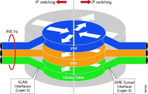
A major benefit of this total separation is the ability to use overlapping IP address spaces. You could have a CORP VRF and a GUEST VRF that both use the 10.0.0.0/8 address space without any conflict, because they exist in separate routing universes.
The following video demonstrates this principle in a lab environment. Seeing it in action, especially with CLI commands, will help solidify your understanding.
How VRFs Work (VRF Lite) | VRFs Part 1
This video from Network Direction shows a practical lab for configuring VRF-Lite. It clearly demonstrates the creation of VRFs, how interfaces are assigned, and how traffic is isolated, including a test with overlapping IPs.
Watch from 01:59 to 07:52. Notice how the router is partitioned into virtual routers. Pay special attention to two key moments: when the IP address is removed after assigning an interface to a VRF (a common 'gotcha'), and how the ping vrf ... command is used to test connectivity within a specific routing instance. Also, see how it handles overlapping IP addresses without issue.
A Practical Look at Configuration and Use Cases
While the next lesson will focus on designing a VRF topology, it's helpful to see the basic commands now. As a CLI user, this will connect the theory directly to practice.
The article below provides excellent, concise tables covering CLI commands and real-world scenarios that are directly relevant to your goals.
VRF Lite Explained: Real-World Use Cases, Commands ...
This article, 'VRF Lite Explained' from Network Journey, is a treasure trove of practical information. It includes tables for commands and use cases, and an excellent FAQ.
First, study the 'Summary: VRF Lite Key Points' table for a quick review. Then, look at the 'Essential CLI Commands' table. Finally, review the 'Real-World Use Case' table, noticing the 'Guest Wi-Fi Segregation' scenario, which is exactly what you plan to do.
To complete your understanding, I strongly recommend reading the FAQ section from that same article. It directly answers common questions you might have.
VRF Lite Explained: Real-World Use Cases, Commands ...
Let's continue with the same article. The FAQ section is particularly valuable.
Read the entire 'FAQs – VRF Lite' section. Pay special attention to questions #8 ('How does VRF Lite help in overlapping IP environments?'), #9 ('Can VRF Lite be used with Layer 3 switches?'), and #10 ('What’s the difference between VRF Lite and traditional VLANs?').
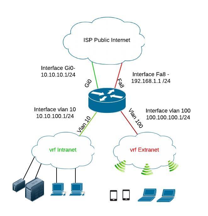
This final reading confirms that VRF-Lite is perfectly suited for your L3 switches and directly addresses the architectural challenges you're looking to solve. Here's a diagram showing a typical enterprise use case.
Conclusion
In this lesson, you've learned the fundamental principles of VRF-Lite. We've moved beyond Layer 2 segmentation with VLANs to understand true Layer 3 isolation.
Key Takeaways:
- VRF-Lite creates virtual routers within a single physical L3 switch or router, providing strong traffic isolation.
- Each VRF maintains its own independent routing table, separate from the global table and other VRFs.
- Isolation is enforced by assigning interfaces (SVIs in your case) to a VRF. Traffic entering that interface can only be routed using that VRF's table.
- This powerful separation allows for enhanced security and the use of overlapping IP addresses without conflict.
You now have the conceptual knowledge of what a VRF is and how it works. In our next lesson, we will put this knowledge into practice by designing a two-VRF topology to separate your internal corporate traffic from guest/internet-only traffic, a core requirement of your project.