Introduction
Hello again! In our last lesson, we explored the "what" and "why" of VRF-Lite, establishing that it's a powerful Layer 3 tool for creating virtual routers within a single physical device. You learned that each VRF has its own isolated routing table, making it ideal for the traffic separation you need in your architecture.
Today, we move from concept to practice. This lesson is all about design. Your learning outcome is to design a two-VRF topology to separate internal corporate traffic from guest/internet-only traffic. We will break this down into three key design decisions:
- Defining the necessary VRFs.
- Mapping your network's interfaces (physical ports and SVIs) to those VRFs.
- Planning the specific routing paths for each VRF to control how traffic gets to the internet.
By the end of this lesson, you will have a clear blueprint for implementing this core security requirement in your network.
The Design Scenario: Corporate vs. Guest Access
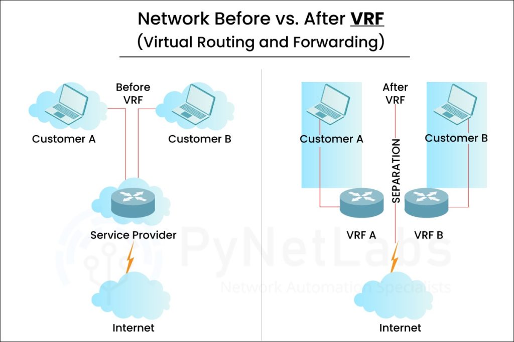
Your primary goal is to provide internet access for two distinct groups—internal employees and guests—while ensuring they are completely isolated from each other.
- Internal (Corporate) Traffic: Needs access to internal servers and the internet, but all internet-bound traffic must first pass through a corporate firewall for security inspection and policy enforcement.
- Guest Traffic: Needs internet access only. It must be completely blocked from reaching any internal corporate resources.
This is a classic use case for VRF-Lite. A single Layer 3 switch can manage both traffic types without them ever mixing.
A Practical Design Example
To understand how to structure this, let's examine a well-documented example that directly mirrors our scenario. The following resource from Noction provides a clear diagram and explanation.
VRF Network configuration and Flexible Netflow
This article outlines a perfect real-world scenario for separating corporate and guest traffic using VRF-Lite. Pay close attention to the topology diagram and the logic of traffic isolation.
Read the section that starts with 'Assume a single network topology depicted in Picture 2'. Focus on how they define two VRFs (RED for guest, BLUE for corporate) and the stated goal that packets from one VRF cannot move to the other. This is the fundamental principle of our design.
As the article explains, the design hinges on creating two separate routing "universes":
- One VRF for corporate traffic (which they call
BLUE). - One VRF for guest traffic (which they call
RED).
Packets entering an interface assigned to the BLUE VRF can only be forwarded using routes found in the BLUE routing table. The RED VRF and its routes are invisible, and vice versa.
Translating Design to Configuration
Now that you see the design, let's connect it to the CLI commands you'll use to implement it. Knowing the commands helps to solidify the design steps in your mind. The following video gives a clear, step-by-step demonstration of the configuration process.
VRF-lite // CCNP ENCOR 350-401 Complete Course
This video from Jeremy's IT Lab demonstrates the fundamental configuration workflow. Seeing this in the CLI will connect the design principles to practical application.
Watch from 06:45 to 13:06. Focus on the three main steps he outlines: Create the VRFs. Assign interfaces to each VRF. Configure routing within the VRFs. Also, take note of the important operational detail he points out: assigning an interface to a VRF removes its existing IP configuration, so it must be reapplied.
The video shows the general process. Now let's look at the specific commands for the Corporate/Guest scenario from the Noction article we reviewed earlier.
VRF Network configuration and Flexible Netflow
Let's return to the Noction article to see the exact commands they used to build the two-VRF topology.
Review the configuration snippets under the 'VRF, Interfaces and Routing' heading. Trace how the design is implemented: VRF Creation: ip vrf RED and ip vrf BLUE create the two routing instances. Interface Assignment: ip vrf forwarding ... is used on both physical interfaces (for uplinks) and VLAN sub-interfaces (for user traffic) to place them into the correct VRF. Routing Configuration: ip route vrf ... is used to create a separate default route for each VRF, pointing to their respective internet gateways. This is the complete execution of the design.
This sequence—create VRF, assign interfaces, configure routes—is the core workflow for deploying a VRF topology.
The Design Blueprint for Your Network
Based on these examples, we can now create a clear design blueprint for your specific architecture.
1. VRF Definitions
First, we define our two virtual routers. We'll give them descriptive names.
vrf CORP_INTERNAL: This VRF will contain all trusted internal networks (users, servers, management, etc.).vrf GUEST_INTERNET: This VRF will be exclusively for guest traffic that needs direct, isolated internet access.
2. Interface and VLAN Mapping
Next, we decide which interfaces go into which VRF. This is where the isolation is enforced.
- For the
CORP_INTERNALVRF:- All SVIs for your internal VLANs (e.g.,
interface Vlan10for Staff,interface Vlan20for Servers) will be assigned to this VRF. - The Layer 3 interface (physical port or SVI) connecting to your corporate firewall will also be assigned to this VRF.
- All SVIs for your internal VLANs (e.g.,
- For the
GUEST_INTERNETVRF:- The SVI for your guest Wi-Fi VLAN (e.g.,
interface Vlan99) will be assigned to this VRF. - The Layer 3 interface connecting to the unfiltered guest internet circuit will be assigned to this VRF.
- The SVI for your guest Wi-Fi VLAN (e.g.,
3. Routing Path Design
Finally, we define the traffic flow for each VRF by creating routes within their isolated routing tables.
- Inside
CORP_INTERNAL:- The L3 switch will automatically have connected routes for all the internal VLANs assigned to this VRF, allowing inter-VLAN routing among them.
- You will add one static default route:
ip route vrf CORP_INTERNAL 0.0.0.0 0.0.0.0 <firewall_next_hop_ip>. This forces all traffic destined for the internet to go to the firewall first.
- Inside
GUEST_INTERNET:- You will add one static default route:
ip route vrf GUEST_INTERNET 0.0.0.0 0.0.0.0 <guest_ISP_gateway_IP>. This sends all guest traffic directly to the internet, bypassing the corporate firewall entirely.
- You will add one static default route:
This three-step blueprint provides a complete, logical design for separating your two traffic types using a two-VRF topology.
Conclusion
In this lesson, we transitioned from the theory of VRF-Lite to the practical steps of designing a topology. You now have a repeatable framework for creating Layer 3 separation in your network.
Key Takeaways:
- A two-VRF design is a standard and effective way to isolate guest traffic from an internal corporate network.
- The design process involves three clear steps: defining the VRFs, mapping interfaces/SVIs, and configuring isolated routes.
- For corporate traffic, the VRF's default route should point to a firewall, enforcing security policy.
- For guest traffic, the VRF's default route should point directly to an ISP gateway, ensuring complete isolation.
You have now successfully designed the VRF topology. The next logical step is to integrate this design with your VLAN plan. In our next lesson, we will focus on the specifics of that integration: planning the assignment of all your VLANs, SVIs, and physical interfaces to their respective VRFs.