Introduction
Hello! In our last lesson, we established the high-level design for separating your network traffic using a two-VRF topology. We defined the CORP_INTERNAL VRF for trusted traffic that needs to go through a firewall, and the GUEST_INTERNET VRF for isolated guest access.
This lesson drills down into the practical details. The learning outcome is to plan the assignment of VLANs, SVIs, and physical interfaces to their respective VRFs. We will move from the logical "what" to the concrete "where." You'll learn exactly which interfaces on your L3 switch get assigned to which VRF to make the separation a reality. This step is the critical link between your logical design and the final device configuration.
The Logic of Assignment: Where Does ip vrf forwarding Go?
The key to remember is that Virtual Routing and Forwarding (VRF) is a Layer 3 concept. The command that places an interface into a VRF, ip vrf forwarding <vrf-name>, is only applied to Layer 3 interfaces. In a multilayer switch environment like yours, this means two types of interfaces are relevant:
-
Switched Virtual Interfaces (SVIs): An SVI (e.g.,
interface Vlan10) is the virtual Layer 3 interface that acts as the default gateway for a VLAN. To place all devices within a VLAN into a specific VRF, you assign that VLAN's SVI to the VRF. All traffic being routed out of that VLAN will then use the VRF's unique routing table. -
Physical Routed Ports: When you need a point-to-point Layer 3 link, such as an uplink to a firewall or an ISP router, you can convert a physical switch port into a routed port (using the
no switchportcommand). This physical interface is then assigned directly to a VRF.
What about regular switch ports?
Standard Layer 2 ports, whether they are access ports (switchport mode access) or trunk ports (switchport mode trunk), are not directly assigned to a VRF. They operate at Layer 2 and are assigned to VLANs. The VRF association happens at Layer 3, via the SVI that serves the VLAN.
A Concrete Example: Intranet and Extranet
Let's look at a practical example that perfectly illustrates these assignment rules. The diagram below shows a common scenario where a single router (or L3 switch) uses VRF-Lite to isolate a corporate "Intranet" from a guest "Extranet."
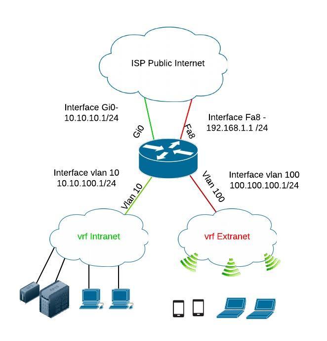
Now, let's examine the configuration that builds this topology.
Cisco VRF Lite Configuration Tutorial with Step-by-Step Example
This article from Networkstraining.com provides the configuration for the exact scenario shown in the diagram. It's an excellent way to see how both SVIs and physical routed ports are assigned to their VRFs.
Please read the configuration under 'Step 2 : Configure VLANs and interfaces and include them in the VRF instances'. As you read the CLI commands, specifically identify: Which command assigns an SVI (like interface Vlan10) to a VRF? Which command assigns a physical routed port (like interface GigabitEthernet0) to a VRF? How are the user-facing physical ports (FastEthernet0 and FastEthernet1) configured? Notice they are Layer 2 access ports assigned to a VLAN, not directly to a VRF.
As you saw in the article, the ip vrf forwarding command is applied under both interface Vlan... and interface GigabitEthernet... configurations, cementing the idea that it's for L3 interfaces only. The user access ports are simply configured for Layer 2 access to their respective VLANs.
To reinforce this key point, let's review a quick video segment.
Free CCNA | VRF | Day 54 (part 3) | CCNA 200-301 Complete Course
This quiz from Jeremy's IT Lab directly addresses which interface types are compatible with VRF.
Watch the final quiz section, from 12:20 to 14:50. Pay close attention to Question 3 and its explanation. It explicitly confirms that VRFs can be configured on SVIs and routed ports on multilayer switches, which is the foundation of our design.
Practical Exercise: Creating Your Assignment Plan
Now it's time to apply this to your network. Let's create the definitive assignment plan that documents which interfaces belong to the CORP_INTERNAL and GUEST_INTERNET VRFs.
Given Information:
Imagine we've already created the following VLAN plan for your multi-building environment:
- VLAN Plan:
- VLAN 10: Staff - Building A
- VLAN 11: Staff - Building B
- VLAN 20: Servers
- VLAN 30: Printers
- VLAN 99: Guest WiFi
- VLAN 100: Network Management
- Physical L3 Connections:
GigabitEthernet1/0/1: Uplink to the corporate firewall.GigabitEthernet1/0/2: Uplink to the dedicated guest ISP router.
Your Task:
Complete the following table to document your VRF assignment plan. For each Layer 3 interface, determine whether it belongs in the CORP_INTERNAL or GUEST_INTERNET VRF based on its purpose.
| L3 Interface | Purpose | Assigned VRF |
|---|---|---|
interface Vlan10 |
Default Gateway for Staff A | |
interface Vlan11 |
Default Gateway for Staff B | |
interface Vlan20 |
Default Gateway for Servers | |
interface Vlan30 |
Default Gateway for Printers | |
interface Vlan99 |
Default Gateway for Guest WiFi | |
interface Vlan100 |
Default Gateway for Management | |
GigabitEthernet1/0/1 |
Uplink to Corp Firewall | |
GigabitEthernet1/0/2 |
Uplink to Guest ISP |
Click here to see the completed assignment plan and reasoning.
Here is the completed plan.
| L3 Interface | Purpose | Assigned VRF |
|---|---|---|
interface Vlan10 |
Default Gateway for Staff A | CORP_INTERNAL |
interface Vlan11 |
Default Gateway for Staff B | CORP_INTERNAL |
interface Vlan20 |
Default Gateway for Servers | CORP_INTERNAL |
interface Vlan30 |
Default Gateway for Printers | CORP_INTERNAL |
interface Vlan99 |
Default Gateway for Guest WiFi | GUEST_INTERNET |
interface Vlan100 |
Default Gateway for Management | CORP_INTERNAL |
GigabitEthernet1/0/1 |
Uplink to Corp Firewall | CORP_INTERNAL |
GigabitEthernet1/0/2 |
Uplink to Guest ISP | GUEST_INTERNET |
Reasoning:
- All internal user, server, and management VLANs (10, 11, 20, 30, 100) are part of the trusted corporate network. Their SVIs must be in the
CORP_INTERNALVRF. - The uplink to the corporate firewall (
GigabitEthernet1/0/1) is the designated path for all corporate internet traffic, so it must also be in theCORP_INTERNALVRF. - The guest VLAN (99) is untrusted and needs isolated internet access. Its SVI must be in the
GUEST_INTERNETVRF. - The uplink to the guest ISP (
GigabitEthernet1/0/2) is the dedicated path for guest traffic, so it must be in theGUEST_INTERNETVRF to complete the isolation.
Conclusion
In this lesson, you created a concrete plan for implementing your VRF design. You now have a clear understanding of how to map different types of interfaces to their appropriate VRFs to achieve Layer 3 traffic isolation.
Key Takeaways:
- VRF assignment is a Layer 3 task. The
ip vrf forwardingcommand is applied to SVIs and physical routed ports. - The VRF of an SVI determines the routing context for all devices in that VLAN.
- The VRF of a routed port determines the routing context for the physical link it represents.
- Layer 2 access and trunk ports are not assigned to VRFs directly; they belong to VLANs.
You have now designed your VLANs, created a VLSM addressing plan, and detailed your VRF topology. You have all the core components of a modern, segmented network design.
Preview of the Next Lesson:
The next module marks the beginning of your Capstone Project. You will start by translating a realistic set of business requirements—locations, user counts, security policies—into a formal technical requirements document. This is the first step in bringing all the skills you've learned together to build a complete enterprise network design from the ground up.