Introduction
Hello! In our previous module, we mastered Variable Length Subnet Masking (VLSM), focusing on how to efficiently allocate Layer 3 IP addresses, right down to the /31s for point-to-point links. You now have a solid toolkit for designing a lean and scalable IP addressing plan.
Today, we're shifting our focus from the Layer 3 logical addresses to the Layer 2 foundation that underpins them. This lesson begins a new module on Strategic L2 Segmentation, and we're starting with the most fundamental tool in the box: the Virtual LAN, or VLAN.
Your goal for this lesson is to explain how VLANs create separate Layer 2 broadcast domains. You already know how to configure VLANs on a switch, but our focus here will be on the "why"—what is actually happening on the network when you assign a port to a VLAN and how this helps you control traffic.
1. The Default: One Big, Noisy Room
Before we can segment a network, we need to understand what we're starting with. By default, a network switch operates like a single, massive, open-plan office.
A broadcast domain is the set of all devices that receive broadcast frames originating from any other device in the same set. By default, all ports on a single switch are in the same broadcast domain. If you connect multiple switches together, this single broadcast domain extends across all of them.
Imagine one of your 48-port switches. If a device on port 1 sends a broadcast, the switch dutifully forwards it out of the other 47 ports. Now, picture that scaled up to the ~1,000 devices in your target architecture, all connected through a dozen switches. A single broadcast from one PC would be sent to every other device on the network. This is not just inefficient; it's a security concern.
To get a clear definition of what a broadcast domain is and how a switch handles these frames by default, please watch the following video.
MicroNuggets: Broadcast Domains Explained
The video 'MicroNuggets: Broadcast Domains Explained' from CBT Nuggets provides a concise explanation of what a broadcast domain is and how switches and hubs treat broadcast traffic by default.
Watch the segment from 00:36 to 04:19. Focus on the definition of a broadcast domain as 'how far a broadcast will be forwarded' and the explanation of how a switch, by default, forwards a broadcast to all other active ports.
This default behavior applies to all BUM traffic:
- Broadcast
- Unknown Unicast (when a switch doesn't know the destination MAC address yet)
- Multicast
In a large network like the one you're designing, allowing BUM traffic to flood everywhere forces every device's CPU to waste cycles processing traffic that is irrelevant to it. This is the problem VLANs were designed to solve.
2. The Solution: Logically Dividing the Switch
A VLAN, or Virtual Local Area Network, allows you to take a single physical switch and carve it up into multiple logical switches. Each logical switch you create represents a separate, isolated broadcast domain.
Think of it as putting up soundproof walls in that large, open-plan office. People in one room can talk and shout all they want (send broadcasts), but the noise won't disturb anyone in the other rooms.
This next short video provides a great animated overview of this concept.
The video 'VLAN Explained' gives a simple, high-level illustration of how VLANs logically group devices and isolate their traffic, regardless of physical location.
Watch from 01:10 to 03:40. Pay attention to how the network traffic is initially mixed together and how creating VLANs isolates the traffic for each department, even though they share the same physical switch.
The core idea is this: instead of buying a separate physical switch for each department or security group, you use one VLAN-capable switch and create multiple, independent virtual networks on it.
3. The Mechanism: How VLANs Control Broadcasts
So, how does this work in practice? The rule is simple: A broadcast frame originating in one VLAN will only be forwarded to other ports within that same VLAN.
The switch uses the VLAN assignment of each port to enforce this rule. When you configure switchport access vlan 10 on an interface, you're telling the switch: "This port is part of the 'VLAN 10' logical switch. Only forward traffic from other VLAN 10 ports here, and only send traffic from here to other VLAN 10 ports."
The following diagram clearly illustrates this broadcast containment.
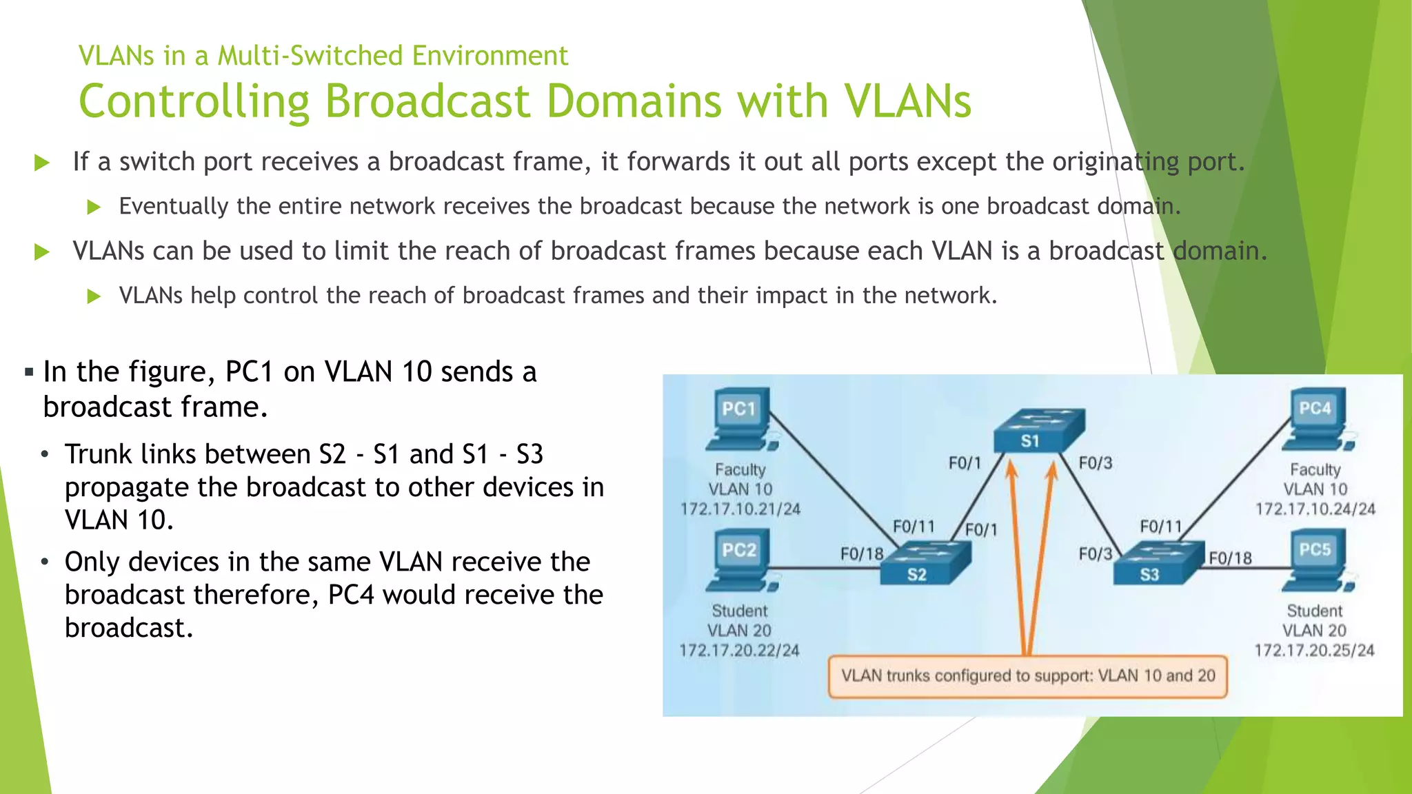
To reinforce this, the following reading from a Cisco Press textbook walks through this exact scenario with helpful explanations.
This PDF chapter from a Pearson textbook provides a detailed breakdown of how VLANs control broadcast domains, comparing a network with and without VLANs.
Read the section 'Controlling Broadcast Domains with VLANs' (starts on page 103). Focus on the contrast between the 'Network Without VLANs' (Figure 3-5) and 'Network with VLANs' (Figure 3-6) examples. This directly explains the concept shown in the image above.
4. Bringing It Back to the CLI
As a CLI user, you've likely configured this hundreds of times. Let's connect the theory to the commands you already know.
When a Cisco switch is first powered on, all ports are in VLAN 1 by default. You can see this with the show vlan brief command. This confirms the "one big broadcast domain" state.
Switch# show vlan brief

VLAN Name                             Status    Ports
---- -------------------------------- --------- -------------------------------
1    default                          active    Fa0/1, Fa0/2, Fa0/3, Fa0/4
                                                Fa0/5, Fa0/6, Fa0/7, Fa0/8
                                                ... (and all other ports)
Now, let's say you configure two new VLANs, 10 (CLIENTS) and 20 (SERVERS), and assign some ports to them.
Switch(config)# interface range fastEthernet 0/1 - 4
Switch(config-if-range)# switchport access vlan 10
Switch(config)# interface range fastEthernet 0/15 - 18
Switch(config-if-range)# switchport access vlan 20
When you run show vlan brief again, you see the result of your work.
Switch# show vlan brief

VLAN Name                             Status    Ports
---- -------------------------------- --------- -------------------------------
1    default                          active    Fa0/5, Fa0/6, ... (remaining ports)
10   CLIENTS                          active    Fa0/1, Fa0/2, Fa0/3, Fa0/4
20   SERVERS                          active    Fa0/15, Fa0/16, Fa0/17, Fa0/18
You have now created three separate broadcast domains on this single physical switch:
- VLAN 1: All the remaining unassigned ports.
- VLAN 10: Ports Fa0/1 through Fa0/4.
- VLAN 20: Ports Fa0/15 through Fa0/18.
A broadcast from a PC on Fa0/1 will now only be sent to Fa0/2, Fa0/3, and Fa0/4. It will not be sent to a server on Fa0/15 or any port still in the default VLAN 1. You have successfully contained the broadcast traffic.
For a comprehensive walkthrough including these CLI examples, the following article is an excellent reference.
VLAN Concept - NetworkAcademy.IO
The article 'VLAN Concept' provides clear explanations and diagrams, and reinforces the concepts with the Cisco CLI commands you're familiar with.
Read the sections 'What are VLANs?' and 'How do VLANs work?'. This will solidify the idea of a physical switch acting as multiple logical switches and how port assignments control broadcast domains.
Conclusion
In this lesson, we established the core function of VLANs. You've moved beyond just knowing the configuration commands to understanding the fundamental principle behind them.
Key Takeaways:
- By default, a Layer 2 switched network forms a single, large broadcast domain. All BUM (Broadcast, Unknown Unicast, Multicast) traffic is flooded to every port.
- A VLAN logically partitions a physical switch into multiple virtual switches.
- Each VLAN is an independent, isolated Layer 2 broadcast domain.
- A broadcast frame sent from a device in one VLAN will only be forwarded to other devices in the same VLAN, effectively containing the traffic.
This principle of isolation is the first and most important step in building the segmented, secure architecture you're aiming for.
In our next lesson, we will build directly on this foundation. We will describe the benefits of VLAN segmentation for performance (broadcast reduction) and security (traffic isolation) and begin developing a strategic VLAN plan for a large network.