Introduction
Hello! In the last module, you learned how to develop a VLAN strategy based on function and security, and then how to estimate the number of hosts each VLAN would need, accounting for future growth. For example, you might have determined that your "Research" VLAN needs 110 hosts, which requires a /25 subnet.
Today, we'll establish the fundamental rule that connects your VLAN plan to your IP addressing scheme. This lesson focuses on a cornerstone of modern network design: explaining the 1:1 relationship between a VLAN and an IP subnet.
Understanding this principle is the critical step that translates your logical network segments (VLANs) into concrete IP address blocks (subnets). It’s the "why" behind the configurations you've likely performed many times. By the end of this lesson, you'll grasp why this rule is non-negotiable for creating a scalable, manageable, and stable network.
The Core Concept: A Tale of Two Layers
To understand the relationship, we first need to be crystal clear about what a VLAN and a subnet are, and where they operate in the OSI model.
- A VLAN (Virtual LAN) is a Layer 2 concept. It works by logically segmenting a physical switch into multiple, isolated broadcast domains. Think of it as taking one 48-port switch and making it behave like several smaller, completely separate switches. Devices in one VLAN cannot directly communicate at Layer 2 with devices in another.
- An IP Subnet is a Layer 3 concept. It's a logical range of IP addresses (e.g., 192.168.1.0/24) where all devices can communicate with each other directly, without needing to go through a router.
Since they operate at different layers, why must they be so tightly linked? Let's start with a clear definition from a resource you might find useful.
How to Select Subnet Sizes for VLANs
This article from CBT Nuggets clearly defines both concepts and immediately states why they are so closely related in network design.
Read the first few sections, from the introduction down to 'When Does a Network Need VLANs and Subnets?'. Focus on the definitions and the core idea that these two technologies are 'intrinsically connected'.
Why One-to-One? The Broadcast Domain Is Key
The mandatory 1:1 mapping comes down to how devices on an IP network find each other: the Address Resolution Protocol (ARP).
When a computer (PC1) wants to send a packet to another computer (PC2) on the same subnet, it needs PC2's MAC address. To get it, PC1 sends an ARP request, which is a Layer 2 broadcast. It essentially shouts, "Who has IP address 192.168.1.50? Tell me, 192.168.1.1!"
This is where the VLAN comes in. A VLAN defines the boundary of that broadcast.
-
Scenario 1 (Failure): Splitting a subnet across two VLANs. Imagine PC1 (192.168.1.50) is in VLAN 10 and PC2 (192.168.1.51) is in VLAN 20. When PC1 sends its ARP broadcast, it's contained entirely within VLAN 10. PC2, in VLAN 20, will never hear it. They are on the same subnet but can't communicate. The network is broken.
-
Scenario 2 (Failure): Putting two subnets in one VLAN. Imagine PC1 (192.168.1.50/24) and PC2 (192.168.2.50/24) are both in VLAN 10. When PC1 wants to talk to PC2, its own networking stack knows that 192.168.2.50 is on a different network. It won't even try to send an ARP request. Instead, it will send the packet to its default gateway to be routed. This defeats the purpose of having them in the same Layer 2 domain and creates a confusing, non-standard configuration.
Therefore, the Layer 2 broadcast domain (the VLAN) and the Layer 3 logical network (the subnet) must perfectly align. One VLAN must map to exactly one Subnet.

This concept is so foundational that it's often a point of clarification for network engineers.
VLANs and Inter-VLAN Routing: The No-Nonsense CCNA Guide to ...
Let's reinforce this with a direct, concise explanation from a practical guide.
In this article, find the 'FAQs' section near the end and read the first question: 'What's the difference between a VLAN and a subnet?'. Note the key sentence: 'VLAN equals Layer 2 broadcast domain. Subnet equals Layer 3 IP range. They usually map 1:1...'. The author also mentions seeing multiple subnets in one VLAN, but correctly notes it complicates things—this is a reference to an advanced and generally discouraged practice called 'secondary addressing'. For all standard designs, stick to the 1:1 rule.
Making it Real: The Role of the Layer 3 Switch and SVI
So, how do you technically implement this 1:1 mapping? This is where your experience with Layer 3 switches comes into play. The glue that binds the Layer 2 VLAN to the Layer 3 subnet is the Switched Virtual Interface (SVI).
- You create a VLAN (e.g.,
vlan 10). This is a pure Layer 2 container. - You then create an SVI for that VLAN (e.g.,
interface Vlan10on a Cisco switch). This is a virtual Layer 3 interface that logically resides within that VLAN. - You assign an IP address to that SVI from the subnet you've allocated for that VLAN (e.g.,
ip address 10.1.10.1 255.255.255.0). - This SVI IP address becomes the default gateway for every device in that VLAN.
When a host in VLAN 10 needs to reach a different subnet, it sends its traffic to the SVI's IP address. The L3 switch then uses its routing table to forward the packet to the correct destination SVI and its corresponding VLAN.
The commands you've likely used many times—interface Vlan... and ip address...—are the physical embodiment of this critical 1:1 mapping.
This short, animated explanation is excellent for visualizing how VLANs create separate subnets and how a Layer 3 switch uses SVIs to connect them.
Watch from 02:31 to 04:43. Pay close attention to two things: How creating VLAN 10 and VLAN 20 immediately results in assigning two different IP address groups (subnets). The role of the Switched Virtual Interfaces (SVIs) as the default gateways for each VLAN, which is what enables communication between them (inter-VLAN routing).
From Concept to Documentation
This 1:1 rule isn't just a technical necessity; it's the foundation of your network documentation. A well-structured IP Address Management (IPAM) document begins by explicitly listing these pairings. This is how you maintain sanity and prevent costly errors like overlapping subnets.
A typical IPAM plan will have columns that look like this:
| VLAN ID | VLAN Name | Subnet Assigned | Gateway IP (SVI Address) | Purpose |
|---|---|---|---|---|
| 10 | USERS | 10.1.10.0/24 | 10.1.10.1 | User workstations & devices |
| 20 | SERVERS | 10.1.20.0/24 | 10.1.20.1 | Physical and virtual servers |
| 30 | VOICE | 10.1.30.0/24 | 10.1.30.1 | VoIP handsets |
| 40 | MGMT | 10.1.254.0/27 | 10.1.254.1 | Switch/Router management |
Let's watch a network designer walk through this exact process.
DESIGNING Subnets for Your Company!
In this clip, you'll see a master subnet for a site being carved up and assigned to specific VLANs. This is a perfect, practical demonstration of creating the 1:1 mapping that forms the basis of an IPAM plan.
Watch the segment from 04:56 to 09:16. Notice how each VLAN (VLAN 10, 20, 30, 40) is explicitly assigned a unique, non-overlapping subnet. This is exactly how you translate a VLAN plan into an addressing plan.
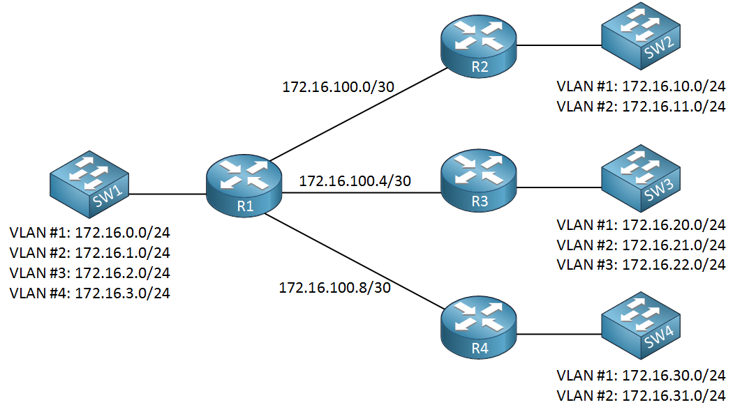
The diagram below shows another example of this documented mapping in a topology.
Conclusion
In this lesson, we established the single most important rule for integrating VLANs and IP addressing.
Key Takeaways:
- The fundamental rule of thumb is one VLAN maps to one IP subnet.
- This rule exists because a VLAN is a Layer 2 broadcast domain, and its boundaries must align with the Layer 3 IP subnet for protocols like ARP to function correctly.
- In modern networks with L3 switches, this relationship is implemented using a Switched Virtual Interface (SVI). The SVI is given an IP address from the subnet and serves as the default gateway for all hosts within that VLAN.
- This 1:1 mapping is the foundation for clear, error-free network documentation (IPAM).
You've now connected the "why" of VLANs (segmentation) with the "how" of IP addressing. In our next lesson, we will begin the practical work of designing the structure of an IP Address Management (IPAM) document and start populating it by formally mapping your VLAN plan to a complete VLSM allocation.