Introduction
Welcome back! In our last lesson, we established the foundational rule of modern network design: the 1:1 relationship between a VLAN and an IP subnet. You learned that a Layer 2 broadcast domain (the VLAN) must align perfectly with a Layer 3 address block (the subnet) for the network to function correctly, and that this link is created by a Switched Virtual Interface (SVI).
Today, we're going to transition from that core principle to formal, professional documentation. Your goal for this lesson is to design the structure of an IP Address Management (IPAM) document for a large network.
Think of this as creating the master blueprint for your network's addressing scheme. A well-structured IPAM document is not just a record; it's a critical tool that prevents errors, simplifies troubleshooting, enables automation, and ensures your network can scale without collapsing into chaos. This is the difference between simply making a network function and truly engineering it.
From Record-Keeping to Network Design
Before we start building our document structure, it's important to distinguish between simply recording what you've configured and proactively designing the network on paper first. The latter is a more disciplined approach that pays dividends on large-scale projects.
Let's explore this idea of "Design-Focused IPAM."
An In-Depth Guide to NetBox for IPAM
This article from NetBox Labs provides a superb introduction to IPAM and distinguishes between two philosophies: merely observing the network versus proactively designing it. This is key to your goal of building a large, well-organized architecture.
Read the sections 'What is IPAM?' and 'Design-Focused vs Observed IPAM'. Focus on understanding why IPAM is more than just a list of addresses and how the 'design-focused' approach provides a 'source of truth' for the network's intended state.
As you can see, our goal is to create a design-focused plan. The IPAM document is the tangible output of this planning process. It's the source of truth that will guide your CLI configurations, not the other way around.
The Essential Columns of an IPAM Document
An effective IPAM document needs to capture all the critical information about each network segment. While a simple spreadsheet can work for learning, we'll design a structure that could be implemented in a spreadsheet or a dedicated IPAM tool like NetBox.
Here are the essential fields (columns) your IPAM structure should include. We'll build this out logically.
-
VLAN Information: This links directly back to your VLAN plan.
VLAN ID: The number (e.g., 10, 20, 30).VLAN Name: A short, descriptive name (e.g.,CORP_USERS,SERVERS_PROD).Description/Purpose: A more detailed explanation of the VLAN's function (e.g., "Corporate user workstations and laptops").
-
Subnet & Addressing Information: This is the Layer 3 information mapped to the VLAN.
Subnet (CIDR): The network address and prefix length (e.g.,10.1.10.0/24).Network Address:10.1.10.0Broadcast Address:10.1.10.255Usable Host Range:10.1.10.1 - 10.1.10.254Gateway IP: The IP address of the SVI for this VLAN (e.g.,10.1.10.1or10.1.10.254).
-
Context and Lifecycle Information: These fields are vital for managing a large network over time.
Location/Site: Which building or campus this segment serves. This is crucial for your multi-building architecture.VRF: The Virtual Routing and Forwarding instance this subnet belongs to. We'll discuss this in detail shortly.Status: The current state of the subnet (e.g.,Active,Reserved,Deprecated).
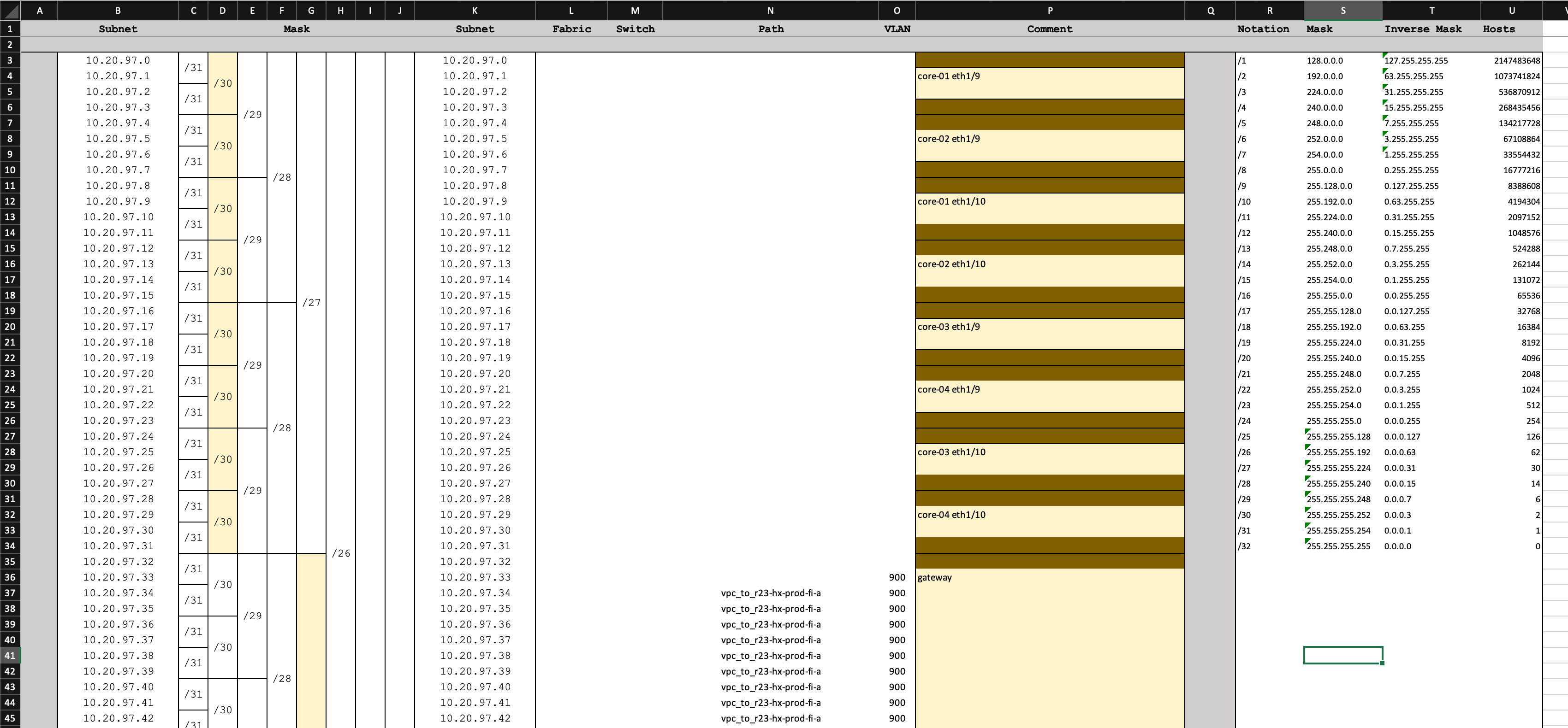
This structure provides a comprehensive, at-a-glance view of your entire addressing plan. The image below shows an example of a spreadsheet-based IPAM document that uses many of these principles.
Designing for Hierarchy and Meaning
For a large network, a flat list of subnets is not enough. A good IPAM structure reflects a logical hierarchy. This often means embedding meaning into the IP addresses themselves, a practice that greatly simplifies operations for anyone working on the CLI.
For example, using the 10.0.0.0/8 block, you could devise a scheme like 10.[SITE].[VLAN_ID].HOST.
- The second octet represents the physical site (e.g.,
10.1.x.xfor Building 1,10.2.x.xfor Building 2). - The third octet represents the VLAN ID (e.g.,
10.1.10.xfor VLAN 10 in Building 1).
This creates a self-documenting address plan. When you're troubleshooting and see an IP like 10.2.30.55, you immediately know it's in Building 2 and belongs to VLAN 30.
How to Design a Basic Subnet in 9 Minutes
This clip from CBT Nuggets explains this exact concept of embedding geographical and functional meaning into the octets of an IP address.
Watch the segment from 06:48 to 08:45. The presenter explains how the second octet can represent a site or area, and the third octet can represent the VLAN. This is a powerful and common design pattern.
This hierarchical thinking is at the core of professional IPAM tools. They don't just store a flat list; they organize IP space into nested blocks.
- Aggregate: The largest block of addresses you own or have been assigned (e.g.,
10.0.0.0/8). - Prefix: The individual subnets you carve out of the aggregate for specific purposes (e.g.,
10.1.10.0/24). A prefix can also be a "container" for smaller prefixes.
Netbox IPAM Prefixes and IP addresses the right way
Let's watch how a real IPAM tool, NetBox, visually represents this hierarchy. This will make the concept of designing a structure much more concrete.
Watch two segments: 01:45 to 04:02: Focus on how a large '/16' data center block is planned and then broken into smaller '/21' subnets. This demonstrates the top-down, hierarchical thinking. 05:34 to 08:16: Observe how NetBox visually nests the prefixes. A /21 'container' is shown to be 25% utilized because two /24 'active' subnets have been allocated from it. This shows how a good structure allows for automatic tracking and management.
Incorporating Your Specific Requirement: VRFs
You specifically mentioned needing to use Virtual Routing and Forwarding (VRF) to separate internet traffic. VRFs are essentially virtual routers inside your physical L3 switch, each with its own independent routing table. This is perfect for securely isolating traffic, such as separating a corporate network from a guest network.
Your IPAM document must account for this. By adding a VRF column, you explicitly document which routing domain each subnet belongs to. This is critical because VRFs allow you to have overlapping IP addresses. For example, you could have a 10.1.1.0/24 subnet in the CORP VRF and another 10.1.1.0/24 in the GUEST VRF, and they wouldn't conflict.

So, your IPAM table might look something like this:
| VLAN ID | VLAN Name | Subnet (CIDR) | VRF | Location | ... |
|---|---|---|---|---|---|
| 10 | CORP-USERS | 10.1.10.0/24 | CORP |
Building 1 | ... |
| 110 | GUEST-WIFI | 10.1.10.0/24 | GUEST |
Building 1 | ... |
Without the VRF column, this would look like a critical addressing error. With it, the design is clear.
Putting It All Together: The Final Structure
Let's summarize the structure of a robust IPAM document. Whether you build this in a spreadsheet for planning or directly into a tool like NetBox, these are the data points you need to capture for each and every subnet.
| Field Name | Example | Purpose |
|---|---|---|
| VLAN ID | 20 |
Layer 2 Identifier. |
| VLAN Name | PROD_SERVERS |
Human-readable name for the L2 segment. |
| Description | Production application and database servers |
Clear statement of the segment's function. |
| Status | Active |
Lifecycle state (e.g., Active, Reserved for future). |
| VRF | CORP_INTERNAL |
The routing domain this subnet belongs to. |
| Location | Building 2 - Data Center |
Physical location for context. |
| Subnet (CIDR) | 10.2.20.0/26 |
The assigned Layer 3 address block. |
| Network Address | 10.2.20.0 |
Calculated for clarity. |
| Usable Range | 10.2.20.1 - 10.2.20.62 |
IP addresses available for hosts. |
| Broadcast Address | 10.2.20.63 |
Calculated for clarity. |
| Gateway IP | 10.2.20.1 |
The SVI address; default gateway for hosts. |
| Total Hosts | 62 |
The capacity of the subnet. |
This structure provides a complete, unambiguous "source of truth" for your network's addressing plan.
Conclusion
In this lesson, you've learned how to design the architecture of an IP Address Management document. This is a critical step that elevates you from simply configuring devices to engineering a scalable and maintainable network.
Key Takeaways:
- An IPAM document is a design-focused tool that serves as the single source of truth for your network's intended state.
- A robust IPAM structure includes columns for VLAN info, detailed subnet calculations, location, status, and the assigned VRF.
- Designing with a hierarchy (e.g.,
10.SITE.VLAN.HOST) makes the address space self-documenting and easier to manage. - Dedicated IPAM tools like NetBox enforce this structure and provide powerful features for automation and validation that are essential for large networks.
You now have the template for your network's master plan. In the next lesson, Populate an IPAM document by mapping a VLAN plan to a VLSM allocation, you'll take the requirements from your VLAN plan and use your VLSM skills to start filling in this document with real, non-overlapping subnets.