Hello! In the last module, we established a complete workflow for writing Verilog code, creating a testbench, and, most importantly, debugging your design visually using a waveform viewer. This ability to see how signals change over time is fundamental to digital design.
Now, we will start using these skills to build actual circuits. This lesson begins our journey into Module 5: Modeling Combinational Logic in Verilog. We'll focus on the most direct way to describe combinational circuits: the continuous assign statement. By the end of this lesson, you will be able to implement any basic logic gate (like AND, OR, NOT, etc.) in Verilog. This is the first step in translating abstract logic functions into concrete, synthesizable hardware descriptions.
1. From Gates to Expressions: Dataflow Modeling
In digital design, we can describe a circuit in several ways. We could list every single logic gate and how they are wired together, which is called structural modeling. Or, we can describe the circuit's behavior at a higher level of abstraction, focusing on how data flows from inputs to outputs. This is known as dataflow modeling.
The assign statement is the primary tool for dataflow modeling in Verilog. It creates what is called a continuous assignment. This means the output is always being updated whenever any of the inputs change, perfectly mimicking the behavior of a physical combinational logic circuit.
The following video provides a clear overview of continuous assignment and how it differs from other types of assignments we will see later.
Continuous Assignment in Verilog
Watch this video, "Continuous Assignment in Verilog" from the channel Dave Moore, to understand the core concept of the assign keyword.
First, watch the segment on the two main types of assignment. Focus on the description of continuous assignment as being like "wiring up a combinational circuit with jumper wires." Next, watch the section on the assign keyword and gate shorthand. This will introduce the syntax and the bitwise operators that represent logic gates.
As the video explained, the assign statement continuously drives a value onto a wire. This is analogous to connecting a power source to one end of a wire on a breadboard—the other end of the wire is continuously driven to that voltage.
2. Syntax and Bitwise Operators
The assign statement allows us to implement logic functions using expressions and operators, rather than by instantiating individual gates. The syntax is straightforward:
assign <net_expression> = <expression>;
The left-hand side (LHS) must be a net type, like a wire. This is a critical rule. The right-hand side (RHS) is an expression that uses bitwise operators to define the logic.
Here are the most common bitwise operators you'll use:
| Operation | Verilog Operator | Example |
|---|---|---|
| Bitwise AND | & |
assign y = a & b; |
| Bitwise OR | ` | ` |
| Bitwise NOT | ~ |
assign y = ~a; |
| Bitwise XOR | ^ |
assign y = a ^ b; |
| Bitwise NAND | ~& |
assign y = ~(a & b); |
| Bitwise NOR | `~ | ` |
| Bitwise XNOR | ~^ or ^~ |
assign y = ~(a ^ b); |
Notice how the assign statement directly maps a logic function to an output wire.
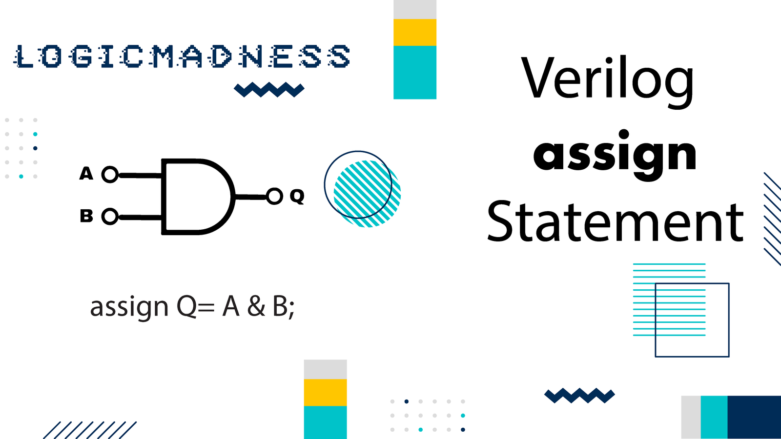
For a detailed reference on the syntax and rules, you can review the following article.
This article from ChipVerify provides a concise and clear explanation of the assign statement.
Read from the beginning down to "Example #1". Pay close attention to the "Rules" section, as it highlights the fundamental constraints of using assign, particularly that the LHS must be a net (like wire).
3. Practical Example: An AND Gate
Let's put this into practice by creating a simple two-input AND gate.
Here is the Verilog code for the module. Create a file named and_gate.v and add this content:
// File: and_gate.v
// Description: A simple 2-input AND gate.

module and_gate (
    input  a,
    input  b,
    output y
);

    // Continuous assignment to model the AND function.
    // y will be updated whenever 'a' or 'b' changes.
    assign y = a & b;

endmodule
Notice that the output y is implicitly a wire by default, which satisfies the rule for assign statements.
Now, let's create a testbench to verify its behavior. Create a file named and_gate_tb.v:
// File: and_gate_tb.v
`timescale 1ns / 1ps

module and_gate_tb;
    // Signals to connect to the DUT
    reg a_tb;
    reg b_tb;
    wire y_tb;

    // Instantiate the Design Under Test (DUT)
    and_gate dut (
        .a(a_tb),
        .b(b_tb),
        .y(y_tb)
    );

    // Setup for waveform dumping (from the previous lesson)
    initial begin
        $dumpfile("and_gate.vcd");
        $dumpvars(0, and_gate_tb);
    end

    // Stimulus block
    initial begin
        // Test all 4 possible input combinations
        {a_tb, b_tb} = 2'b00; #10;
        {a_tb, b_tb} = 2'b01; #10;
        {a_tb, b_tb} = 2'b10; #10;
        {a_tb, b_tb} = 2'b11; #10;


        #10; // Wait a bit longer at the end
        $finish; // End the simulation
    end

endmodule
Your Turn: Compile, Simulate, and Verify
Now, use the workflow you learned in the previous lesson:
- Compile:
iverilog -o and_gate_sim and_gate.v and_gate_tb.v - Run:
vvp and_gate_sim - View:
gtkwave and_gate.vcd
In GTKWave, add a_tb, b_tb, and y_tb to the wave viewer. Does the output y_tb behave as you expect for an AND gate? It should only be high when both inputs are high.
Mini-Challenge
Modify the assign statement in and_gate.v to implement:
- An OR gate (
a | b). - An XOR gate (
a ^ b).
After each change, re-run the simulation and check the waveform. This will give you a feel for how easily you can define different logic functions.
4. A Critical Rule: assign Drives wire, Not reg
One of the most common beginner mistakes is trying to use an assign statement to drive a signal that has been declared as a reg.
This is illegal in Verilog and will cause a compiler error.
module bad_design (
    input a, b,
    output reg out // ERROR: Declared as reg
);
    // This line will cause a compilation error because 'out' is a reg.
    assign out = a & b;
endmodule
The reason for this rule is fundamental to how Verilog models hardware:
- A
wirerepresents a physical connection. It doesn't store a value; it is simply driven by whatever is connected to it.assignmodels this continuous connection. - A
regrepresents a storage element, like a flip-flop. It holds a value until it is explicitly told to update. This is done inside procedural blocks (always,initial), which we will cover in detail later.
The takeaway is simple: If you are using an assign statement to drive an output, ensure it is a wire type. Module outputs are wire by default, so you often don't need to declare them explicitly.
Conclusion
In this lesson, you've learned the most direct method for modeling combinational logic in Verilog. The assign statement allows you to describe the flow of data through logic expressions, which synthesis tools can then translate into an efficient gate-level circuit.
Key Takeaways:
- Dataflow modeling uses
assignstatements to describe how outputs are derived from inputs. - An
assignstatement creates a continuous assignment, meaning the output is updated immediately whenever an input changes. - Verilog uses bitwise operators (
&,|,~,^, etc.) to represent logic gates within expressions. - A continuous assignment can only drive a net type, such as a
wire. It cannot drive areg.
In our next lesson, we will continue exploring assign statements by looking at a special, compact way to model multiplexers using the ternary operator. This will further demonstrate the power of dataflow modeling for creating common digital components.