Welcome back! In our previous lesson, we investigated one of the most common issues in RTL design: the unintended latch. You learned that latches are inferred when an output in a combinational always block isn't assigned a value for every possible input combination, and you saw how to prevent this by either fully specifying all branches or using default assignments.
Today, we'll put that knowledge into practice by modeling another fundamental building block: the decoder. We will focus on using a case statement within an always @(*) block to implement this logic. This is an industry-standard technique that results in clean, readable, and efficient hardware descriptions. By the end of this lesson, you'll be able to model a decoder from its truth table using this powerful Verilog construct.
1. What is a Decoder?
At its core, a decoder is a combinational circuit that converts a binary input code into a specific output signal. For an N-bit input, a decoder typically has output lines. Its primary function is to assert exactly one of these output lines based on the value of the input code.
For example, a 2-to-4 decoder has two inputs and four outputs. If the input is 2'b00, the first output line is activated. If the input is 2'b01, the second is activated, and so on. This "one-hot" output format (where only one bit is 'hot' or active) is used in many applications, such as memory address decoding or selecting which sub-unit of a larger circuit should be active.
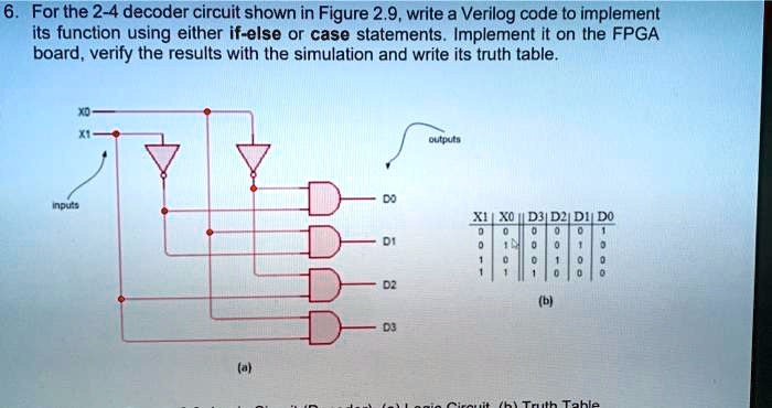
The following video provides a concise overview of a 2-to-4 decoder, including its truth table and the logic expressions derived from it.
Decoder 2: 4 | verilog code for 2 to 4 decoder in data flow and behavioral description
This video from Explore Electronics explains the basic functionality of a 2-to-4 decoder.
Please watch the first part of the video covering the decoder's function and truth table. Don't worry about the logic expressions or the gate-level circuit diagram for now; focus on understanding the relationship between the inputs and the one-hot outputs.
2. The case Statement: A Better Tool for the Job
While you could model a decoder using a series of if-else if statements, this can become cumbersome and less readable as the number of inputs grows. A much better tool for this kind of "one-of-many" selection logic is the case statement.
The case statement compares an expression against a list of possible values and executes the statements associated with the first match it finds. For hardware design, this structure maps very naturally to a multiplexer or, in our case, decoder logic.
To learn the syntax and advantages of the case statement, watch the following video.
#27 "case" statement in verilog | if-else vs CASE || when to use if-else and case in verilog
This video from Component Byte introduces the Verilog case statement and compares it to if-else.
Please watch the following segments: Start with the introduction to what a case statement is. Then, learn why it's preferred over if-else for many conditions. Next, review the syntax, paying close attention to the default keyword. Understand how a case statement in an always @(*) block creates purely combinational logic. Finally, watch the performance comparison with if-else.
As the video highlights, a key reason to prefer case for decoder logic is that it implies a parallel structure to the synthesis tool, whereas a nested if-else chain implies priority. For a decoder, all inputs should be treated with equal priority, making case a more accurate representation of the hardware's intent.
Most importantly, the default clause in a case statement is our primary tool for preventing unintended latches, directly applying what we learned in the last lesson.
3. Modeling a Decoder in Verilog
Now let's combine these concepts to write the Verilog for a decoder. We will use an always @(*) block with a case statement to model a 3-to-8 decoder. This module will have a 3-bit input and an 8-bit output.
The following article provides a perfect, concise example of this.
3x8 Decoder Implementation in Verilog
This article by RAO MUHAMMAD UMER on Medium provides a clear and direct implementation of a 3x8 decoder using a case statement.
Read the introduction and the "Explanation" section that describes the decoder_3_8 module. Study the Verilog code provided.
Let's break down the key parts of the code from the article:
// Code based on the resource [LINK](https://medium.com/@raoumer160903/3x8-decoder-implementation-in-verilog-9a8b659650c0)
module decoder_3_8(
    output reg [7:0] y,
    input [2:0] i
);

    always @(*) begin
        case (i)
            3'b000: y = 8'b00000001;
            3'b001: y = 8'b00000010;
            3'b010: y = 8'b00000100;
            3'b011: y = 8'b00001000;
            3'b100: y = 8'b00010000;
            3'b101: y = 8'b00100000;
            3'b110: y = 8'b01000000;
            3'b111: y = 8'b10000000;
            default: y = 8'b00000000; // Important!
        endcase
    end
endmodule
Key points to notice:
output reg [7:0] y: The outputyis declared asregbecause it is assigned from within a proceduralalwaysblock.always @(*): This sensitivity list tells the simulator and synthesis tool to re-evaluate the block whenever any of the inputs (iin this case) change, creating combinational logic.case (i): Thecasestatement selects which branch to execute based on the value of the 3-bit inputi.3'b000: y = 8'b00000001;: Each case item maps a specific 3-bit input value to a unique 8-bit one-hot output value.default: y = 8'b00000000;: This is critical. While ourcasestatement covers all 8 possible values of the 3-bit inputi, explicitly adding adefaultis excellent practice. It prevents latch inference in cases where not all inputs are specified and makes the designer's intent clear. Here, we choose to output all zeros if an unexpected value (like3'bxxz) were to appear in simulation.
This case-based structure is very powerful and readable, even for more complex decoding tasks. For instance, decoding a 4-bit binary number to drive a seven-segment display uses the exact same pattern, just with different output values.
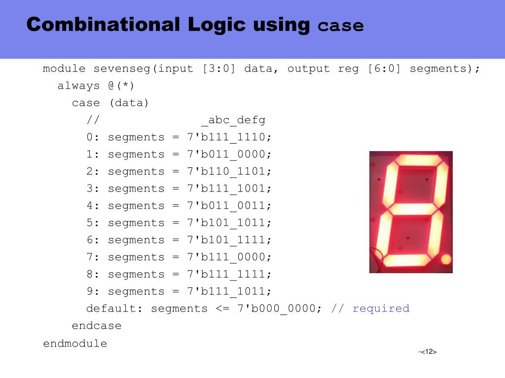
4. Your Turn: Code a 2-to-4 Decoder
Now it's your turn to apply what you've learned. Based on the 3-to-8 decoder example and the truth table from the beginning of the lesson (Image LINK), write the Verilog module for a 2-to-4 decoder named decoder_2_to_4.
- Inputs: A 2-bit wire named
i. - Outputs: A 4-bit
regnamedy. - Use an
always @(*)block and acasestatement. - Remember to include a
defaultcase.
Solution
// Verilog module for a 2-to-4 decoder
module decoder_2_to_4 (
    output reg [3:0] y,
    input [1:0] i
);

    always @(*) begin
        case (i)
            2'b00: y = 4'b0001;
            2'b01: y = 4'b0010;
            2'b10: y = 4'b0100;
            2'b11: y = 4'b1000;
            default: y = 4'b0000;
        endcase
    end

endmodule
Conclusion
In this lesson, you've successfully combined your knowledge of always blocks and latch avoidance to build a standard digital component. The case statement is the perfect tool for describing decoders, resulting in Verilog that is not only functionally correct but also clearly communicates the design's intent to both simulators and synthesis tools.
Key Takeaways:
- A decoder converts an N-bit binary input into a -bit one-hot output.
- The Verilog
casestatement is the ideal structure for modeling decoder logic within analways @(*)block. - Using
caseimplies parallel logic, which is a better fit for decoders than the priority logic implied byif-elsechains. - Always include a
defaultcase to fully specify the logic and prevent the inference of unintended latches.
In our next lesson, we will move on to another essential combinational circuit: the adder. We'll learn how to implement a parameterized N-bit adder, which will introduce the powerful concept of creating flexible and reusable Verilog modules.