Hello! In our last lesson, we designed a decoder, a combinational circuit that selects one output line based on a binary input. This is a core component for addressing and selection in digital systems.
Today, we move from selection to arithmetic, tackling one of the most fundamental building blocks of any computer: the adder. We'll focus on the full adder, a circuit capable of adding a single column of binary digits, including a carry from a previous column. This component is the heart of the Arithmetic Logic Unit (ALU) found in every processor.
Our goal is to design a full adder from basic logic gates. We will follow a systematic process: understanding the need, defining the behavior with a truth table, deriving the logic expressions, and finally, constructing the gate-level circuit.
1. From Decimal to Binary Addition
You're already an expert at addition in base 10. When you add 8 + 5, you get 3 and carry a 1. Binary addition works the same way, but the rules are much simpler.
To get started, let's watch a quick, intuitive explanation of how binary addition works, just like the column-by-column addition you do with decimal numbers.
Learn how computers add numbers and build a 4 bit adder circuit
Watch the first minute of "Learn how computers add numbers and build a 4 bit adder circuit" by Ben Eater.
Focus on the column-by-column addition example. Notice how adding 1 + 1 results in a sum of 0 and a carry of 1, and adding 1 + 1 + 1 (including a carry-in) results in a sum of 1 and a carry of 1.
The key insight is that for any column past the first one, you aren't just adding two bits (A and B), but three bits: A, B, and the carry-in from the previous column ().
A circuit that only adds two bits is called a half adder. A circuit that adds three bits (A, B, and ) is called a full adder. Since we want to build circuits that can add numbers of any size, the full adder is the essential component we need.
2. Defining the Full Adder's Behavior
A full adder is a combinational circuit with:
- Three inputs: , , and (Carry-In).
- Two outputs: (Sum) and (Carry-Out).
To formally define its behavior, we create a truth table that lists all possible input combinations and the corresponding correct outputs.
Let's watch a video that systematically builds this truth table.
Half Adder and Full Adder Explained | The Full Adder using Half Adder
Watch this section from "Half Adder and Full Adder Explained" by ALL ABOUT ELECTRONICS.
Pay close attention to how the presenter fills out the Sum and Carry-out columns for each of the eight possible input combinations. This process is just applying the rules of binary addition we saw earlier.
For your reference, here is the complete truth table for a full adder:
| (Sum) | (Carry-Out) | |||
|---|---|---|---|---|
| 0 | 0 | 0 | 0 | 0 |
| 0 | 0 | 1 | 1 | 0 |
| 0 | 1 | 0 | 1 | 0 |
| 0 | 1 | 1 | 0 | 1 |
| 1 | 0 | 0 | 1 | 0 |
| 1 | 0 | 1 | 0 | 1 |
| 1 | 1 | 0 | 0 | 1 |
| 1 | 1 | 1 | 1 | 1 |
Take a moment to verify a few rows. For example, the row A=1, B=0, Cin=1 represents 1 + 0 + 1, which equals 2 in decimal. In binary, 2 is 10, so the Sum is 0 and the Carry-Out is 1.
3. Deriving Logic and Building the Circuit
Now that we have the truth table, we can derive the Boolean expressions for the and outputs and implement them with logic gates.
Deriving the Boolean Expressions
We'll use algebraic manipulation to simplify the sum-of-products expressions from the truth table. The following reading provides a concise derivation for both outputs.
Full Adder - Logical Expressions
Please read the sections "Logical Expressions for SUM" and "Logical Expression for C-OUT" from the GeeksforGeeks article.
Focus on how the initial sum-of-products expressions are simplified using Boolean algebra laws to arrive at the final, compact equations. You can skip the K-map details if mentioned and focus on the algebraic steps.
From this process, we get two elegant expressions:
-
Sum (S):
The sum output is '1' whenever an odd number of inputs are '1'. This is the definition of the XOR function. -
Carry-Out ():
The carry-out is '1' whenever two or more inputs are '1'. The simplified expression is:
Implementing with Logic Gates
Now we can translate these expressions directly into a circuit diagram. The Ben Eater video provides an excellent, intuitive walkthrough of building the circuit from these exact logical ideas.
Learn how computers add numbers and build a 4 bit adder circuit
Return to the Ben Eater video "Learn how computers add numbers and build a 4 bit adder circuit".
First, watch the section on building a simple two-input adder (a half-adder) to see the A XOR B and A AND B logic. Then, watch as he expands this into a full adder by adding the logic for the Carry-in. Notice how the final circuit perfectly matches the Boolean expressions we just derived.
The resulting circuit diagram looks like this:
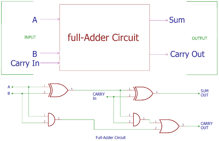
This circuit is the complete design of a full adder using basic logic gates, which fulfills our main goal for this lesson.
4. An Alternative View: Building a Full Adder from Half Adders
There is another common and insightful way to construct a full adder: by combining two half adders. This highlights the modularity of digital design.
- A half adder takes two inputs (A, B) and produces a sum () and a carry ().
To add three bits (), you can first add and using one half adder. Then, you take its sum and add it to using a second half adder. The final carry-out is produced by OR-ing the carry outputs from both half adders.
The following video demonstrates this construction.
Half Adder and Full Adder Explained | The Full Adder using Half Adder
Watch this section from "Half Adder and Full Adder Explained" to see this alternative construction.
Observe how the circuit is built by connecting two half-adder blocks and an OR gate. This modular approach is very common in digital design.
Thinking about the full adder in this way reinforces the idea of building complex components from simpler ones, a key principle you'll use throughout your career.
Conclusion
In this lesson, we successfully designed a full adder, a critical component for computer arithmetic. We started from the basic rules of binary addition and moved through a formal design process to create a complete gate-level circuit.
Here are the key takeaways:
- A full adder is a combinational circuit that adds three bits—, , and a —to produce a two-bit result: a Sum () and a Carry-Out ().
- The behavior is defined by a truth table, from which we can derive the simplified Boolean expressions:
- This logic can be implemented directly using XOR, AND, and OR gates.
- A full adder can also be constructed from two half adders and an OR gate, demonstrating modular design principles.
Now that we know how to add a single column of bits, the next logical step is to add multi-bit numbers. In our next lesson, we will learn how to construct a 4-bit ripple-carry adder by connecting four of the full adders we designed today.