Hello! In our last lesson, we focused on the multiplexer, a component that selects one of many inputs to route to a single output. This is a fundamental operation for managing data flow in digital systems.
Today, we will explore a complementary building block: the decoder. In many ways, a decoder performs the reverse operation. It takes a binary code as input and activates one specific output line out of many. This makes it essential for tasks like selecting which memory chip to enable or which device on a bus should listen for data.
Our goal for this lesson is to learn how to design a 2-to-4 decoder from basic logic gates. We'll follow a systematic process, starting from a high-level description and ending with a complete gate-level circuit diagram.
1. What is a Decoder?
A decoder is a combinational circuit that converts a binary code from its N input lines into a signal on one of its 2N output lines. For any given input combination, only one output is asserted (typically set to '1'), while all other outputs remain de-asserted ('0').
Think of it like a mail sorter. The input is an address (a binary number), and the decoder activates the correct mailbox (the output line) corresponding to that address. This ability to "decode" a binary number into a specific selection is fundamental in computers for addressing memory, I/O ports, and other resources.
To start, let's watch a short video that introduces the concept of decoders and how they relate to selecting one of many possibilities.
Combinational Devices 2: Decoders
Watch this brief introduction from the "Combinational Devices 2: Decoders" video by Down to the Wires.
Pay close attention to the main idea presented: using fewer input lines to select one of a larger number of possibilities. The video introduces the term "minterm," which you'll see is directly related to how a decoder works.
As the video explained, each output of a decoder corresponds to a specific minterm of the input variables. We'll see this clearly as we design our own.
2. Designing a 2-to-4 Decoder
Let's design a 2-to-4 decoder. As its name implies, it has:
- 2 input lines (let's call them and ). These form a 2-bit binary number.
- 4 output lines (let's call them ).
- A common and very important extra input: an Enable line (). This acts as an on/off switch for the entire component.
The design process follows three clear steps:
- Define the behavior with a truth table.
- Derive the Boolean expressions for each output.
- Construct the logic circuit from the expressions.
The following reading from TutorialsPoint will guide us through this entire process.
Please read the section on the 2-to-4 decoder from the article "Digital Electronics - Decoders".
Focus on the block diagram, the complete truth table (including the enable input 'E'), the derived Boolean expressions, and the final logic circuit diagram. This single section covers our entire design process from start to finish.
Let's break down the key information from that reading.
Step 1: The Truth Table
The truth table is the formal specification of our decoder. It defines what the outputs should be for every possible combination of inputs. Based on the reading, the truth table for a 2-to-4 decoder with an enable line is:
| E | A | B | Description | ||||
|---|---|---|---|---|---|---|---|
| 0 | X | X | 0 | 0 | 0 | 0 | Decoder is disabled |
| 1 | 0 | 0 | 0 | 0 | 0 | 1 | Input is 00, select |
| 1 | 0 | 1 | 0 | 0 | 1 | 0 | Input is 01, select |
| 1 | 1 | 0 | 0 | 1 | 0 | 0 | Input is 10, select |
| 1 | 1 | 1 | 1 | 0 | 0 | 0 | Input is 11, select |
Note: 'X' denotes a "don't care" condition. If the enable is 0, the outputs are all 0 no matter what A and B are.
Step 2: Boolean Expressions
Now, we derive a Boolean expression for each output. We look for the rows where the output is '1'. This process should be familiar from your work with sum-of-products form.
- For : The output is 1 only when . The corresponding Boolean expression is .
- For : The output is 1 only when . The expression is .
- For : The output is 1 only when . The expression is .
- For : The output is 1 only when . The expression is .
Notice how each expression is a product of all three input variables (), matching one specific minterm. A decoder is essentially a minterm generator.
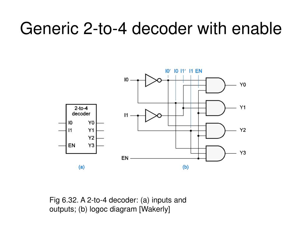
Step 3: Logic Circuit Implementation
Each Boolean expression is a simple product term, which can be implemented with a single AND gate. Since our expressions have three variables, we will need 3-input AND gates.
- The expression requires a 3-input AND gate with inputs , , and .
- The expression requires a 3-input AND gate with inputs , , and .
- ...and so on for and .
We will also need two NOT gates (inverters) to generate and from the inputs and .
The final circuit combines these elements as shown below.
3. Visualizing the Design Process
To reinforce your understanding, let's watch a video that walks through the creation of the truth table and the logic circuit in a dynamic way.
Decoder Basics and 2-to-4 Decoder: Working, Truth Table, Circuit, and Designing
Watch these clips from the "Decoder Basics" video by Engineering Funda. It clearly demonstrates the steps we just took.
First, watch the creation of the truth table. Notice how the presenter systematically fills it out based on the inputs and the enable pin. Next, see how the circuit is constructed from the logic expressions. The video provides a clear step-by-step drawing of the gates and their connections, matching the diagram we saw earlier.
This completes our design. We have successfully designed a functional 2-to-4 decoder from its initial requirements all the way down to a diagram of basic logic gates.
Conclusion
In this lesson, we designed a 2-to-4 decoder, another crucial combinational logic component. We saw how its function is to select one of its outputs based on a binary input code.
Here are the key takeaways:
- A decoder converts an N-bit binary input into an active signal on one of its 2N outputs.
- The design process involves creating a truth table, deriving Boolean expressions for each output, and implementing those expressions with basic logic gates (primarily AND and NOT gates).
- An enable input is a common feature that allows the entire decoder to be switched on or off.
- A decoder is fundamentally a minterm generator, where each output corresponds to a specific minterm of the input variables.
In our next lesson, we will shift from selection and decoding to arithmetic by designing a full adder. This component is the heart of any circuit that needs to perform addition, forming the basis for the Arithmetic Logic Units (ALUs) found in all processors.