Welcome to the next lesson in our journey through digital design. In our previous session, we successfully built a Moore-type Finite State Machine (FSM) using the industry-standard two-always-block style. This gave us a solid foundation by separating the FSM's memory (the state register) from its logic.
Today, we'll build on that knowledge to implement a Mealy-type FSM. The core Verilog structure will feel very familiar, but we will focus on the one crucial difference: how the output is generated. A Mealy machine's output depends on both the current state and the current inputs, making it more responsive. Our goal is to master how to model this behavior cleanly and efficiently in Verilog.
1. The Anatomy of a Mealy FSM
Let's start by formalizing the distinction between Moore and Mealy machines. As you learned previously, a Moore FSM's outputs are a function of the present state only. In contrast, a Mealy FSM's outputs depend on both the present state and the current inputs.
The Fundamentals of Efficient Synthesizable Finite State Machine
This document provides concise, formal definitions of Moore and Mealy FSMs.
Please read section 2, "Mealy and Moore FSMs". Pay close attention to the definition of a Mealy FSM and how it differs from a Moore FSM.
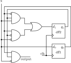
This difference has a direct impact on the hardware structure. In a Mealy machine, there is a direct combinational path from the circuit's inputs to its outputs, as well as from the state registers.
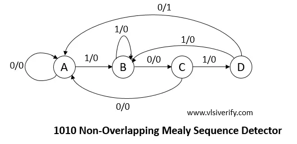
This is also reflected in the state diagrams. Instead of outputs being associated with the state itself (inside the circle), outputs are associated with the transitions (on the arrows), labeled as input/output.
2. Implementing a Mealy FSM in Verilog
To implement a Mealy FSM, we adapt the two-always-block style we used for the Moore machine. The structure remains largely the same:
-
Block 1: Sequential State Register: An
always @(posedge clk)block that updates the state. This block does not change. It's still responsible only for synchronously updatingcurrent_statebased onnext_state. -
Block 2: Combinational Logic: An
always @(*)block that calculates thenext_stateand, for a Mealy machine, also the outputs. Since the outputs depend on the current state and inputs—the same signals the next-state logic uses—it's natural and efficient to combine them into a single combinational block.
The following video provides an excellent walkthrough of implementing a '101' Mealy sequence detector using this exact structure.
49 - Verilog Description of FSMs
This video from Anas Salah Eddin provides a clear, step-by-step implementation of a Mealy FSM in Verilog.
Please watch the main implementation section, which covers building the Mealy FSM. As you watch, focus on: The always @(posedge clk) block for the state register. Note that it's identical to what we used for the Moore FSM. The always @(*) block for the next-state logic, which uses a case statement to describe the state transitions. How the output logic is implemented. The video shows a continuous assign statement: assign y = (state_register == s2) && x;. This single line perfectly captures the Mealy machine's behavior: the output y is '1' only if the machine is in state s2 and the input x is '1'.
A Complete Example with Good Practices
While a continuous assign statement is great for simple outputs, a more scalable approach is to define the outputs inside the combinational always block. A recommended practice is to set a "default" value for all outputs at the beginning of the block and then only specify changes within the relevant states. This prevents accidental latch creation and makes the code's intent clearer.
The paper you read earlier provides a great example of this style.
FSM Design - Two Always Block Style
This section of the paper presents a full Verilog example of a Mealy FSM using the recommended two-block style.
Review the code in Example 1 - fsm_cc4_2 design. Pay close attention to the always @(state or ...) block. Notice the default output assignment gnt = 1'b0; at the top of the block. Then, see how the output gnt is asserted to 1'b1 only inside the BBUSY and BWAIT states. This structure cleanly separates next-state logic and output logic within the same combinational block.
3. The Behavior of Mealy Outputs
A critical consequence of the output logic being combinational is that the output can change as soon as an input changes, without waiting for the next clock edge. This means a Mealy FSM can react faster than a Moore FSM. However, it also means the output might not be stable for a full clock cycle, which can be a design consideration.
The same video you just watched has a great segment comparing the waveforms of a Mealy and a Moore machine.
49 - Verilog Description of FSMs
This segment compares simulation waveforms to highlight the timing differences between Mealy and Moore outputs.
Watch the portion explaining the simulation results. Observe how the Mealy output (y_melee) can appear and disappear between clock edges, reacting instantly to input changes. In contrast, the Moore output (y_moore) changes only after a clock edge and remains stable for the entire cycle.
This behavior is neither good nor bad; it's a fundamental trade-off. Mealy machines are faster, while Moore machines produce cleaner, synchronous outputs that are often easier to integrate with other synchronous parts of a system.
4. Practice: Design Your Own Mealy FSM
Let's apply what you've learned. Here again is the state diagram for a '1010' non-overlapping Mealy sequence detector.
Based on this diagram, think about how you would structure the Verilog code using the two-always-block style we've just discussed.
Questions to guide your thinking:
-
State and Output Declarations:
- You have four states (A, B, C, D). How many bits do you need for your
stateandnextregisters? - You have one input (
x) and one output (y). How would you declare them?
- You have four states (A, B, C, D). How many bits do you need for your
-
State Register Block:
- Write down the
always @(posedge clk ...)block. It will look exactly like the ones we've seen today. Assume an active-low reset that returns to state A.
- Write down the
-
Combinational Logic Block:
- Start by writing the shell:
always @(*)withbeginandend. - What will be your default output assignment for
yat the top of this block? - Inside the
case (state)statement, what would the logic for stateClook like? - Now for the most important part: the output. Identify the single transition in the entire diagram where the output is
1. Write a single continuousassignstatement that would correctly model this output behavior.
- Start by writing the shell:
Click to see a possible solution
-
Declarations: You need 2 bits for 4 states. The declarations would be:
parameter A = 2'b00, B = 2'b01, C = 2'b10, D = 2'b11; reg [1:0] state, next; input x, clk, rst_n; output y; -
State Register:
always @(posedge clk or negedge rst_n) begin if (!rst_n) state <= A; else state <= next; end -
Combinational Logic:
- The default output would be
y = 1'b0;if implemented inside the always block. - The logic for state
Cwould be:if (x) next = D; else next = A; - The output
yis1only when the FSM is in stateDand the inputxis0. Theassignstatement would be:
assign y = (state == D) && (x == 0); - The default output would be
Conclusion
In this lesson, you have successfully extended your FSM design skills to include Mealy machines. You now understand the fundamental difference in their output logic and how to implement this efficiently in Verilog.
Key Takeaways:
- A Mealy FSM's output is a function of the current state AND current inputs.
- This is implemented in Verilog by adapting the two-always-block style: the sequential state register block remains the same, while the combinational output logic is typically modeled in the same
always @(*)block as the next-state logic. - The most direct way to code a Mealy output is with a continuous
assignstatement that checks both the state and relevant inputs:assign output = (state == ...) && (input == ...);. - Mealy outputs are faster but can change asynchronously between clock edges, whereas Moore outputs are synchronous to the clock.
You have now learned how to design and implement both Moore and Mealy FSMs, the two foundational building blocks of complex sequential logic. But how do we know if our designs are correct? In the next module, we will dive into Verification, where you'll learn how to write a self-checking testbench to automatically test your FSMs and other designs.