Hello! In our last lesson, we mastered the skill of translating a visual state diagram into a structured state transition table. This table is the perfect blueprint for what we're going to do today: implement a Finite State Machine (FSM) in Verilog.
Our goal is to write the Verilog code for a Moore-type FSM. Specifically, we will use the industry-standard two-always-block style. This is a crucial technique because it clearly separates the sequential (memory) part of the FSM from the combinational (logic) part, leading to more readable, maintainable, and reliable hardware.
This lesson will connect the theory of FSMs directly to the practical skill of writing synthesizable RTL code, moving you one step closer to your goal of being ready for your bootcamp.
1. The Anatomy of an FSM in Verilog
From a hardware perspective, any FSM can be broken down into three fundamental parts. Understanding these is key to structuring your Verilog code correctly.
- State Register: This is the memory of your FSM. It's a set of flip-flops that stores the machine's current state. It updates its value only on a clock edge.
- Next-State Logic: This is a block of combinational logic. Its job is to look at the current state and the current inputs to decide what the next state should be.
- Output Logic: This is another block of combinational logic. For a Moore machine, its job is simple: determine the output values based only on the current state.
The image below shows how these three blocks connect. The State Register is sequential (clocked), while the Next-State and Output Logic are purely combinational.

To ensure you have a solid grasp of these components, please read the brief descriptions in the following article.
How to Implement a Finite State Machine (FSM) in Verilog
This section from VLSIFacts provides a concise definition of the three main parts of an FSM.
Read the section titled "What is a Finite State Machine (FSM)?". Focus on understanding the distinct roles of the State Register, Next State Logic, and Output Logic.
2. The Two-Always-Block Coding Style
Now, let's translate this three-part structure into Verilog. The recommended method is called the "two-always-block" style because it uses one always block for the sequential logic and a second always block for the combinational logic.
Here is the breakdown:
- State Definitions: First, we define our states using
parameterorlocalparam. This makes the code readable by using names (likeIDLE,STATE_A) instead of raw binary values. - Block 1: State Register (Sequential): This block models the state register flip-flops.
- It's sensitive to the clock edge:
always @(posedge clk). - It handles the synchronous update:
current_state <= next_state;. - It also manages the reset condition.
- Crucially, it uses non-blocking assignments (
<=).
- It's sensitive to the clock edge:
- Block 2: Next-State Logic (Combinational): This block models the combinational logic that calculates
next_state.- It's sensitive to all its inputs:
always @(*). - It typically uses a
casestatement that switches oncurrent_state. - Crucially, it uses blocking assignments (
=).
- It's sensitive to all its inputs:
- Output Logic (Combinational): For a Moore FSM, this is also combinational logic. It can be implemented inside the combinational
alwaysblock or, more cleanly, using continuousassignstatements.
This video provides an excellent, step-by-step walkthrough of creating a Moore FSM using exactly this structure.
How to Write an FSM in SystemVerilog (SystemVerilog Tutorial #1)
This video from Charles Clayton demonstrates how to code a Moore FSM in SystemVerilog, which shares the same core principles as Verilog.
Watch from the start to the end of the implementation. As you watch, pay close attention to: Defining the states using an enumerated type (enum), which is the SystemVerilog equivalent of using parameter. The first always block, which is sequential and updates the current state. The second always block, which is combinational and determines the next state. The assign statement for the Moore output, which depends only on the current_state.
3. A Worked Example: Traffic Light Controller
Let's solidify this with a classic example: a simple traffic light controller that cycles through Red, Green, and Yellow states. The following video walks through an implementation. It first shows a less-optimal single-block approach and then refactors it into the preferred two-block style. This contrast clearly shows why the separation is beneficial.
MODELING FINITE STATE MACHINES
This video from the "Hardware Modeling Using Verilog" series explains how to improve an FSM design by splitting it into two always blocks.
Please watch the section on the modified two-block implementation. Notice how this change solves the problem of unintentionally creating extra flip-flops for the output. The first always @(posedge clk) block is purely sequential and only updates the state variable. The second always @(state) block is purely combinational and computes the light output based on the state. A synthesizer will correctly infer combinational logic (a decoder) from this block, not registers.
To give you a complete, clean reference, here is the full code for a traffic light controller using the three-part structure (two always blocks for logic, plus state/signal declarations).
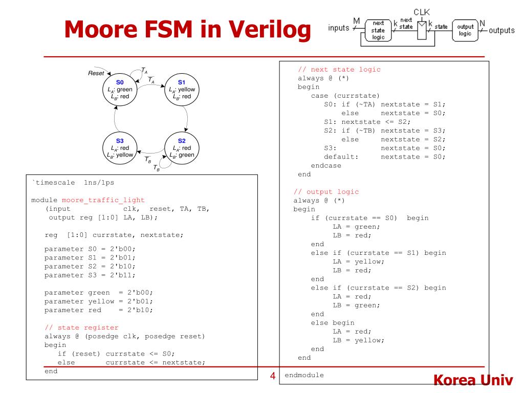
Here is a slightly different implementation from VLSIFacts. This version uses three always @(*) blocks, separating next-state logic and output logic into their own blocks for maximum clarity. This is also an excellent and common practice.
Example: Traffic Light Controller (Moore FSM)
This article provides the full Verilog code for a Moore FSM traffic light controller, clearly separating the three main components.
Review the code in the "Example: Traffic Light Controller (Moore FSM)" section. The code is broken into three distinct, well-commented blocks: State register: A sequential block updating state. Next state logic: A combinational block determining next_state. Output logic: A combinational block assigning the light output. Notice how this structure directly mirrors the block diagram we saw at the beginning of the lesson.
Conclusion
Today, you've learned the most important and robust method for implementing FSMs in Verilog. By separating the design into distinct sequential and combinational blocks, you create code that is not only easier to read and debug but also gives the synthesis tools the best chance to create efficient hardware.
Key Takeaways:
- A Moore FSM's Verilog implementation is structured into three parts: a state register, next-state logic, and output logic.
- The two-always-block style is the industry standard for FSM implementation.
- Block 1 (
always @(posedge clk)) is for the sequential state register. It uses non-blocking assignments (<=). - Block 2 (
always @(*)) is for the combinational next-state logic. It uses blocking assignments (=). - The Moore output logic is also combinational, depending only on the current state. It can be a simple
assignstatement or part of a combinationalalwaysblock.
In our next lesson, we will build on this foundation to implement a Mealy-type FSM. You will see that the structure is very similar, with one key change to the output logic, reflecting the fundamental difference between the two machine types.