Hello! Welcome to the first lesson in our new module on Advanced RTL Design and Synthesis Concepts. In the previous modules, you've built a strong foundation in digital logic, Verilog, and, most recently, creating robust, self-checking testbenches.
Now, we'll start applying those skills to explore more complex and critical aspects of modern chip design. We'll begin with a fundamental element of any sequential circuit: the reset signal. Its job is to force a circuit into a known, predictable starting state. How this reset is applied has significant implications for the circuit's timing, reliability, and synthesis.
In this lesson, you will learn to compare synchronous and asynchronous resets and, most importantly, identify the appropriate use cases for each. This is a crucial topic and a frequent subject of discussion in design reviews and technical interviews.
1. The Need for Reset
Before comparing reset strategies, let's briefly touch on why we need them in the first place. When you power on a digital chip, the internal storage elements—the flip-flops—can wake up in random states (either 0 or 1). A state machine could start in an invalid state, a counter could start at a random value, and the whole system would behave unpredictably.
A reset signal solves this by forcing all flip-flops to a known initial value, ensuring the system starts operating correctly. The video below gives a quick, high-level overview of this concept.
Which to use , Asynchronous reset or synchronous reset ? Resets Explained || Reset synchronizer!!
This video from Karthik Vippala introduces the core purpose of resets in chip design.
Watch the first minute, from the beginning to the introduction of the two types of reset. Focus on the key idea: a reset brings the design to a "known state."
There are two main ways to apply this reset: synchronously (in sync with the clock) or asynchronously (independent of the clock).
2. Synchronous Reset
A synchronous reset is a reset signal that only affects the circuit on an active clock edge. The reset logic is treated just like any other data input to the flip-flop; it must satisfy setup and hold times relative to the clock.
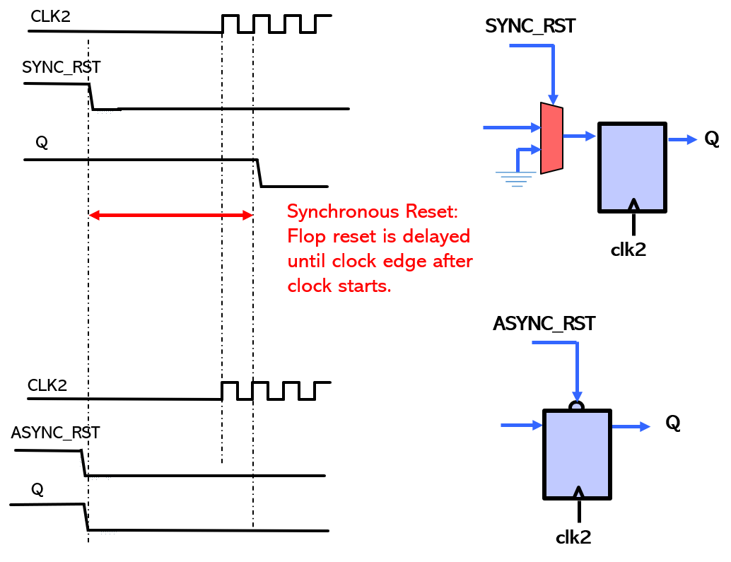
Verilog Implementation
In Verilog, a synchronous reset is coded by placing the if (reset) condition inside an always block that is sensitive only to the clock edge.
// D flip-flop with active-low synchronous reset
module dff_sync_reset (
    output reg q,
    input      d,
    input      clk,
    input      rst_n // 'n' for active-low
);

    always @(posedge clk) begin
        if (rst_n == 1'b0) begin // Check for reset only on the positive clock edge
            q <= 1'b0;
        end else begin
            q <= d;
        end
    end

endmodule
Notice that rst_n is not in the sensitivity list (@(posedge clk)). This is the defining characteristic of a synchronous reset in RTL.
Pros and Cons
Synchronous resets have distinct advantages and disadvantages. The following video explains this clearly.
Which to use , Asynchronous reset or synchronous reset ? Resets Explained || Reset synchronizer!!
This segment from Karthik Vippala's video details how synchronous resets work.
Watch the section covering synchronous resets. Pay close attention to the Verilog code, the resulting waveform, and the potential problem highlighted at the end: what happens if the reset pulse is too short and occurs between clock edges?
To summarize:
- Advantages:
- Fully Synchronous: The design is easier to analyze with static timing analysis (STA) tools because the reset adheres to the same clocking rules as all other signals.
- Glitch Filtering: Since the reset is only sampled at the clock edge, any spurious glitches on the reset line that occur between edges are ignored.
- Disadvantages:
- Requires a Clock: The circuit cannot be reset until a stable clock is available. This can be an issue during power-up.
- Pulse Width Dependency: The reset signal must be active for at least one full clock cycle to guarantee it is captured. A very short reset pulse might be missed entirely.
- Larger Logic: Synthesis tools often infer a multiplexer or extra logic in the data path to the flip-flop, which can slightly increase area and delay.
3. Asynchronous Reset
An asynchronous reset, as the name implies, acts independently of the clock. When the reset signal is asserted, it forces the flip-flop to its reset state immediately, regardless of what the clock is doing.
Look again at the "Synchronous and Asynchronous Reset Comparison" image, this time focusing on the bottom half. Notice how Q drops to 0 the moment ASYNC_RST goes low, without waiting for a clock edge. This is possible because flip-flops in standard cell libraries have a dedicated, high-priority pin for asynchronous reset.
Verilog Implementation
To model this in Verilog, you must add the reset signal to the sensitivity list of the always block.
// D flip-flop with active-low asynchronous reset
module dff_async_reset (
    output reg q,
    input      d,
    input      clk,
    input      rst_n
);

    // The sensitivity list now includes the reset signal's edge
    always @(posedge clk or negedge rst_n) begin
        if (rst_n == 1'b0) begin // This check is triggered by a falling edge on rst_n OR a rising edge on clk
            q <= 1'b0;
        end else begin
            q <= d;
        end
    end

endmodule
The negedge rst_n in the sensitivity list is what makes the reset asynchronous. The if statement now has the highest priority; the logic will trigger and execute the reset branch whenever rst_n falls to 0.
Pros and Cons
Asynchronous resets solve the problems of synchronous resets, but they introduce a new, very critical one.
Which to use , Asynchronous reset or synchronous reset ? Resets Explained || Reset synchronizer!!
These sections of the video explain asynchronous resets and their major challenge.
First, watch the part explaining asynchronous resets. Note how it solves the short-pulse problem from the previous section. Then, continue watching the crucial segment about the disadvantage and the solution. This is the most important part of the lesson. Focus on understanding the problem of reset de-assertion (also called reset removal) and the reset synchronizer circuit used to solve it.
Let's break this down:
- Advantages:
- Immediate Reset: The reset action is fast and does not depend on the clock. You can reset the chip even if the clock signal has not yet stabilized after power-on.
- Disadvantages:
- Metastability on De-assertion: This is the critical issue. While asserting the reset is safe, de-asserting it (releasing it) is dangerous. If
rst_ngoes from 0 back to 1 very close to a rising clock edge, it violates the flip-flop's recovery time (similar to setup time) or removal time (similar to hold time). This can push the flip-flop into a metastable state, where its output is unpredictable for a short time.
- Metastability on De-assertion: This is the critical issue. While asserting the reset is safe, de-asserting it (releasing it) is dangerous. If
4. The Industry-Standard Solution: Reset Synchronizer
As you just saw in the video, we can't leave the risk of metastability unresolved. The standard solution is to use an asynchronous reset with a synchronous release, often implemented with a reset synchronizer.
The idea is simple but powerful:
- An external, fully asynchronous reset signal is brought into the chip.
- This signal is fed into a small two-flip-flop synchronizer circuit.
- The output of this synchronizer is then distributed as the main reset signal to the rest of the design's flip-flops.

This circuit, from the 24x7fpga.com article, shows the implementation. The external rst_asyn asynchronously resets the two flip-flops. When rst_asyn is de-asserted, the synchronizer ensures that rst_main is de-asserted cleanly on a clock edge, preventing metastability from propagating into your main design.
This hybrid approach gives you the best of both worlds:
- The ability to reset the chip immediately on power-up (asynchronous assertion).
- A safe, predictable release from reset that is synchronized to the clock (synchronous de-assertion), avoiding metastability.
5. Comparison and Use Cases
So, which one should you use? The answer depends on the context. The image below provides an excellent summary of the trade-offs.

Here is the practical guidance for most ASIC designs:
-
For the Global Reset: Use an asynchronous reset with a reset synchronizer. The chip's primary reset pin should be asynchronous to ensure it can be reset at power-on before clocks are stable. This signal must then be synchronized before being used by the internal logic. This is the most common and robust strategy.
-
For Internal Resets: Use a synchronous reset. If a block of logic needs to generate a reset signal for another block within the same clock domain, a synchronous reset is preferred. It's simpler, requires less area, and is inherently safe from the de-assertion and glitch issues associated with asynchronous signals.
Conclusion
You've now explored one of the most fundamental trade-offs in sequential design. Understanding how and when to use synchronous versus asynchronous resets is key to creating reliable, robust hardware.
Key Takeaways:
- Synchronous Reset: Activated on a clock edge. It's robust against glitches and simplifies timing analysis but requires a running clock and a sufficiently wide reset pulse.
- Asynchronous Reset: Activated immediately, independent of the clock. It's essential for power-on reset but suffers from a critical flaw: de-asserting it near a clock edge can cause metastability.
- Reset Synchronizer: The standard industry solution to the asynchronous reset problem. It combines asynchronous assertion with synchronous de-assertion, providing both immediate reset capability and a safe release from reset.
- Use Case: Use an asynchronous reset (with a synchronizer) for the main, chip-level reset. Use synchronous resets for internally generated reset signals within a single clock domain.
In our next lesson, we will dive into pipelining, a powerful architectural technique used to increase the clock speed and throughput of a digital circuit.