Hello! In our last lesson, we examined how synchronous and asynchronous resets are used to control a circuit's starting state. We saw that managing timing around signals like resets is critical for reliability. Today, we'll explore another powerful technique that focuses on timing, but this time with the goal of dramatically improving performance.
This lesson introduces pipelining, a fundamental architectural strategy in high-performance digital design. You will learn how pipelining is used to increase a circuit's throughput—the rate at which it can process data. We'll explore what pipelining is, how it works, and the important trade-offs it involves. This concept is essential for designing fast and efficient digital systems, from simple processing units to complex CPUs.
1. The Performance Bottleneck: Long Combinational Paths
In digital circuits, the maximum speed at which you can run your clock is determined by the longest path a signal must travel through combinational logic between two registers. This is known as the critical path.
Let's say you have a complex calculation that takes 10 ns to complete.
- The latency of this operation is 10 ns (the time for one input to produce one output).
- The clock period () must be at least 10 ns.
- This means the maximum clock frequency is .
- The throughput (how many results you can get per second) is also 100 million operations per second.
If you try to run the clock faster than this, say with an 8 ns period, the calculation won't have finished by the time the next clock edge arrives to capture the result. This leads to incorrect, corrupted data.
The core idea of pipelining is to solve this problem by breaking up that long, slow combinational path.

2. The Pipelining Solution: Divide and Conquer
Pipelining divides a large combinational block into a series of smaller, faster stages, separated by registers (which are typically D flip-flops). Each stage performs a piece of the total computation.
The following video from MIT OpenCourseWare provides an excellent explanation of this process.
This video introduces the concept of pipelined circuits, explaining how they improve throughput.
First, watch the introduction which defines latency and throughput for a basic combinational circuit. Next, see how inserting registers creates pipeline stages, allowing parts of the circuit to work in parallel on different data. Finally, understand how pipelining affects the clock period, latency, and throughput. This section highlights the fundamental trade-off.
Let's summarize the key consequences of pipelining:
-
Higher Clock Frequency: The clock period is no longer determined by the total combinational delay, but by the delay of the slowest stage. If our 10 ns path is broken into five stages, each taking 2 ns, the new clock period can be just over 2 ns (plus register overhead). This allows for a much higher clock frequency ( MHz).
-
Increased Throughput: Because the clock is faster, the circuit can accept a new input and produce a new output every clock cycle. Once the pipeline is full, results stream out at a much higher rate. In our example, the throughput increases from 100 million to nearly 500 million operations per second.
-
Increased Latency: There's a trade-off. A single piece of data now has to pass through multiple registers on its way from input to output. If there are pipeline stages, it will take clock cycles for the first result to appear. The total latency is now . While each individual operation takes longer to complete, the overall processing rate of a stream of data is much higher.
Here is a more concrete example showing an adder circuit being pipelined.
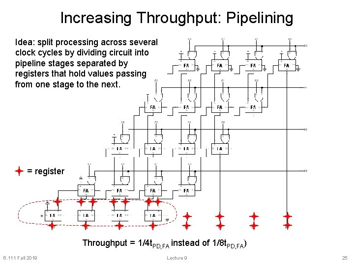
3. Visualizing and Implementing a Pipeline
To better understand how data moves through a pipelined system, we can use a pipeline diagram. It shows which data is in which stage during each clock cycle.
This segment from the same MIT video explains how to use a pipeline diagram.
Watch the section on pipeline diagrams. Notice how each input (X_i, X_i+1, etc.) progresses diagonally through the stages over successive clock cycles.
From Concept to Verilog
Now, how do we actually build this in Verilog? The process involves:
- Analyzing the data dependencies in your computation to decide where to break it into stages.
- Creating registers to hold the intermediate results between stages.
- Writing
always @(posedge clk)blocks to perform the logic for each stage and capture the results in the pipeline registers.
The next video demonstrates this process with a practical example.
This video walks through the design and Verilog implementation of a three-stage pipeline.
First, observe how a hypothetical computation is broken down into three stages based on data dependencies. Next, see how registers are used to store intermediate values and "forward" necessary inputs to later stages. Pay close attention to how input D is passed from stage to stage. Then, look at the Verilog implementation. Notice that all the stage logic is within a single always @(posedge clk) block, using non-blocking assignments (<=) to update the pipeline registers simultaneously. This is the standard coding style. Finally, watch the conclusion showing the simulation results. It clearly shows that after an initial delay to fill the pipeline, a new output is generated every single clock cycle.
The Verilog implementation reinforces what you already know about sequential logic. Each pipeline stage is a block of combinational logic, and the registers between them are modeled exactly like the registers you've built before, updated on the positive edge of the clock.
Conclusion
Pipelining is a cornerstone of modern digital design, enabling the high speeds we expect from processors and other hardware. By trading a small increase in latency for a large gain in throughput, we can build much more powerful systems.
Key Takeaways:
- Pipelining is the technique of inserting registers into long combinational logic paths to break them into shorter, faster stages.
- The primary benefit is a significant increase in throughput, as the circuit can operate at a much higher clock frequency.
- The maximum clock frequency of a pipelined circuit is limited by the propagation delay of its slowest stage (plus register setup and clock-to-q times).
- The main trade-off is an increase in latency: a single operation takes more clock cycles to complete. Latency = (Number of Stages) × (Clock Period).
In the next lesson, we will look more closely at the impact of pipelining on latency. Then, we will begin assembling these advanced concepts to understand the structure of a simple processor datapath, seeing how components like ALUs and registers come together in a pipelined fashion.