Hello! In our last lesson, we took a major step forward by building a self-checking testbench. We learned how to automatically compare the output of our Design Under Test (DUT) against an expected result, freeing us from manually inspecting waveforms.
We briefly touched on using the $readmemh system task to load pre-computed expected outputs from a file. Today, we'll explore the other, more common use of this technique: loading the input stimulus itself from an external file. This approach is powerful because it separates your test data from your testbench logic, making it far easier to create, manage, and reuse complex test scenarios.
By the end of this lesson, you will be able to use the $readmemh system task to create a data-driven testbench that loads its input vectors from an external file.
1. Why Load Stimulus From a File?
So far, we've generated stimulus directly in our testbench, either by explicitly setting values or using a for loop.
// Previous approach: Hardcoded stimulus
initial begin
    {a, b, sel} = 3'b000; #10;
    {a, b, sel} = 3'b001; #10;
    // ... and so on
end
This is fine for simple cases, but it has drawbacks:
- Scalability: For a 32-bit adder, you can't manually type out every input combination.
- Maintenance: If you want to add or change a test case, you have to edit the Verilog code.
- Reusability: The test logic is tightly coupled with the test data. It's hard to run the same testbench with a different set of inputs.
By moving the stimulus into a separate file, we create a data-driven testbench. The testbench becomes a generic engine that reads vectors from a file and applies them to the DUT. This is a much more flexible and professional approach.
2. The Tools: $readmemh and $readmemb
Verilog provides two primary system tasks for reading data from a file into a memory array within your simulation.
$readmemh: Reads hexadecimal values.$readmemb: Reads binary values.
The article "Initialize Memory in Verilog" provides an excellent and concise overview of the syntax for these tasks and the required format for the data file.
This article from Project F clearly explains the syntax and provides practical examples for using $readmemh and $readmemb.
Please read the sections "Verilog Syntax", "Memory File Syntax", and "Verilog Examples". Pay close attention to: The arguments: The file name and the memory array name are required. The start and end addresses are optional. File formatting: Values should be separated by whitespace (spaces, tabs, or newlines). You can also use // for comments. Memory declaration: Notice how the Verilog memory is declared, for example: reg [15:0] ex1_memory [0:3];. This creates an array of four 16-bit registers.
As you read, it's important to understand the connection between the three key parts:
- The Data File (
.txtor.mem): A simple text file with your input values. - The Verilog Memory (
regarray): A variable in your testbench that will store the data from the file. - The System Task (
$readmemh/$readmemb): The command that performs the loading operation.
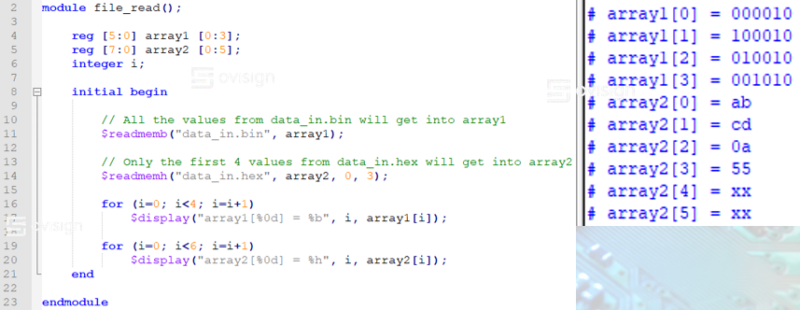
3. A Step-by-Step Walkthrough
Now, let's see this in action. The following video walks through a complete example of reading stimulus from a file to test a RAM module. While the DUT is different, the testbench principles are exactly what we're learning.
File Reading and Writing in Verilog || explanation with working Verilog code || very important
The video "File Reading and Writing in Verilog" demonstrates the full workflow.
Please watch the following sections: Syntax Explanation: This will be a good review of the $readmemh syntax you just read about. File Format and Location: This part clearly shows how the data file should look and, crucially, that it needs to be in the same folder where you run your simulation. Complete Example: Watch how the testbench reads the addresses and applies them to the RAM module, demonstrating the core loop of a data-driven test.
4. Practical Application: A Data-Driven MUX Testbench
Let's apply this concept to upgrade the self-checking MUX testbench from our previous lesson. Instead of using a for loop to generate inputs 0 through 7, we will read these values from a file.
Step 1: Create the Stimulus File
First, create a simple text file named mux_stimulus.txt. This file will contain all the input combinations for our 2:1 MUX. The inputs are {sel, b, a}, which is a 3-bit vector. We will write them in hexadecimal.
mux_stimulus.txt
// Input vectors {sel, b, a}
0 // 000
1 // 001
2 // 010
3 // 011
4 // 100
5 // 101
6 // 110
7 // 111
Note: Ensure this file is saved in the same directory where you will run your simulation.
Step 2: Modify the Testbench
Now, we'll modify tb_mux_2_to_1_self_checking.v. The core self-checking logic remains the same, but we will replace the stimulus generation part.
The article "Test Bench Data Files in Verilog" shows a very similar pattern for testing an XOR gate. We will follow that structure.
This section from the FPGA-Coding blog provides a clear, complete example of a data-driven testbench.
Focus on the xor_test module. Notice the pattern: An integer i is declared for the loop. A memory test_data is declared to hold the vectors. $readmemb is called inside the initial block. A for loop iterates through test_data, applying each vector to the DUT inputs.
Following this pattern, here is our updated, data-driven testbench for the 2:1 MUX:
tb_mux_2_to_1_data_driven.v
`timescale 1ns / 1ps

module tb_mux_2_to_1_data_driven();

    // DUT signals
    reg  tb_a;
    reg  tb_b;
    reg  tb_sel;
    wire tb_y;

    // --- New additions for data-driven testing ---
    localparam NUM_TESTS = 8;
    reg [2:0] stimulus_vectors [0:NUM_TESTS-1]; // Memory to hold vectors
    integer i; // Loop iterator

    // --- Self-checking variables (from previous lesson) ---
    reg    expected_y;
    integer error_count = 0;

    // Instantiate the DUT
    mux_2_to_1 dut (
        .a(tb_a),
        .b(tb_b),
        .sel(tb_sel),
        .y(tb_y)
    );

    // Stimulus and Checking Block
    initial begin
        $display("Starting Data-Driven MUX Test...");

        // 1. Load stimulus from file into our memory array
        $readmemh("mux_stimulus.txt", stimulus_vectors);

        // 2. Loop through the loaded vectors
        for (i = 0; i < NUM_TESTS; i = i + 1) begin
            // 3. Apply stimulus by unpacking the vector
            {tb_sel, tb_b, tb_a} = stimulus_vectors[i];

            // Wait for propagation delay (same as last lesson)


            #1;

            // 4. Determine expected result (Reference Model)
            expected_y = tb_sel ? tb_b : tb_a;

            // 5. Compare actual vs. expected (Scoreboard)
            if (tb_y !== expected_y) begin
                $display("--> FAILED on vector %0d: {sel,b,a} = %b", i, stimulus_vectors[i]);
                $display("    Output: Expected %b, Got %b", expected_y, tb_y);
                error_count = error_count + 1;
            end


            #9; // Wait until the next test case
        end

        // 6. Final Report (same as last lesson)
        if (error_count == 0) begin
            $display("-------------------------------------------");
            $display("All %0d tests PASSED!", NUM_TESTS);
            $display("-------------------------------------------");
        end else begin
            $display("-------------------------------------------");
            $display("TESTS FAILED with %0d error(s).", error_count);
            $display("-------------------------------------------");
        end

        $finish; // End simulation
    end
endmodule
Analysis of the Changes:
- Memory Declaration: We added
reg [2:0] stimulus_vectors [0:7];to create a memory that can hold eight 3-bit vectors. - Load Data: The first thing inside the
initialblock is$readmemh("mux_stimulus.txt", stimulus_vectors);. This populates our memory array. - Loop and Apply: The
forloop now iterates from0toNUM_TESTS-1. Inside the loop,stimulus_vectors[i]retrieves one vector from our memory, and we assign it to the DUT inputs using concatenation:{tb_sel, tb_b, tb_a} = stimulus_vectors[i];. - Decoupled Logic: Notice how clean this is. If you want to test a different sequence of inputs, you only need to change
mux_stimulus.txt. The Verilog testbench code itself remains untouched.
Conclusion
Congratulations! You have now learned how to create a data-driven testbench, a fundamental technique for scalable and maintainable verification. By separating your test vectors into an external file, you make your testing process more robust and professional.
Key Takeaways:
- Data-driven testbenches separate test data from test logic.
- The
$readmemh(hex) and$readmemb(binary) system tasks are used to load data from a file into a Verilog memory array. - The workflow is: create a text file with stimulus, declare a
regarray in the testbench, use$readmemh/$readmembto load the data, and then loop through the array to apply each stimulus vector to the DUT. - This approach is highly scalable and is standard practice for testing complex digital designs.
In our testbenches so far, we've ended the simulation by explicitly calling $finish. In the next lesson, we will formalize this, exploring how to use $finish to automatically and reliably terminate a simulation once all tests are complete, which is essential for running automated test suites.