Hello! Welcome to your third lesson.
In our last session, we got acquainted with the TIA Portal environment. You learned how to navigate between the Portal and Project views and successfully created a new project with an S7-1200 CPU. This set the stage for our work today.
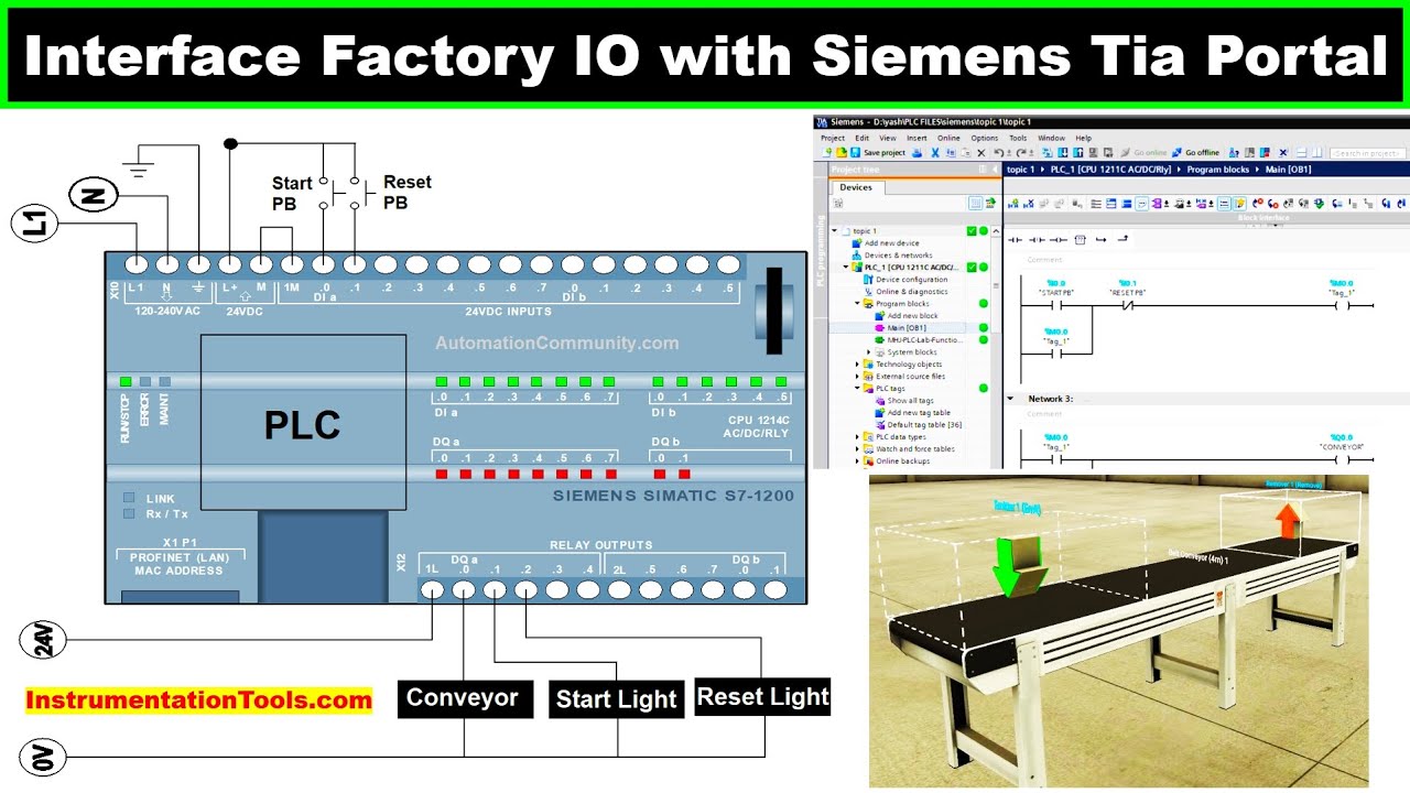
This lesson is all about bringing your physical hardware setup into the digital world. Our goal is to configure hardware and assign I/O addresses in TIA Portal. This process is the software equivalent of building and wiring your PLC control panel. You are essentially creating a map that tells the CPU which components are connected and where to find their data. A correct hardware configuration is the non-negotiable foundation upon which all control logic is built.
From Physical Rack to Digital Twin
Imagine you have a physical S7-1200 CPU and a box of I/O modules. You would mount them on a DIN rail and connect them. In TIA Portal, we do the same thing virtually in the Device View.
The project you created in the last lesson should have opened to the Device View, showing your CPU on a virtual rack. Let's explore how to add more components.
Your main tools for this task are:
- Device View (Center): Your virtual workspace where you "assemble" your PLC system.
- Hardware Catalog (Right): Your "parts bin," containing all the Siemens hardware you can add to your project.
- Inspector Window (Bottom): The details panel where you configure the properties of any selected component.
Adding and Configuring Hardware Modules
Let's start by building a more complete PLC rack, adding digital and analog I/O modules. Since you have experience with S7-1200 and S7-1500, we'll look at examples for both.
The following video provides a clear, step-by-step walkthrough of adding various modules to an S7-1200 rack and configuring their properties.
Device and Hardware configuration in TIA Portal (TIA Portal)
Watch this video from JohnGvideo to see how to populate your PLC rack with different I/O modules from the Hardware Catalog.
Watch from 01:03 to 05:03. The presenter demonstrates: Adding a specific S7-1200 CPU to the project. Using the Hardware Catalog to find and add Digital Input/Output (DI/DO) and Analog Input/Output (AI/AO) modules by dragging them onto the rack.
While the process is similar for the S7-1500, its modular nature is more pronounced. The next video focuses on an S7-1500 "Compact" CPU, which has some I/O already built-in, and then adds an extra module.
TIA Portal: Hardware Configuration
This video from Hegamurl focuses on an S7-1500, showing how to identify its built-in I/O and add expansion modules.
Watch from the beginning to 02:43 and then from 07:40 to 08:35. Notice how the compact CPU already has I/O points, and how easily a new module can be dragged from the catalog to an empty slot on the rack.
Network Configuration: Giving Your PLC an Address
Just like a computer on a network, your PLC needs an IP address to communicate. This address allows your programming computer, HMI panels, and other devices to connect to it. Setting this is one of the first and most important configuration steps.
Let's return to the first video to see how this is done.
Device and Hardware configuration in TIA Portal (TIA Portal)
The presenter will now show you how to access the CPU's properties to set its PROFINET interface address.
Watch from 05:03 to 06:17. In the Inspector Window, under Properties > PROFINET interface > Ethernet addresses, you can define a unique IP address and subnet mask for your PLC.
The Heart of Configuration: Assigning I/O Addresses
Now we arrive at the most critical part of this lesson: I/O addressing. Every single input terminal (for a sensor) and output terminal (for an actuator) on your PLC needs a unique address. This address is how your program code will read the state of a sensor or command an actuator to turn on.
In Siemens, these addresses have a specific format:
- Identifier:
%Ifor Input (German: Eingang),%Qfor Output (German: Ausgang). - Data Type:
Xfor a single bit,Bfor a byte (8 bits),Wfor a word (16 bits),Dfor a double word (32 bits). - Address: The byte and bit number.
For example, %IX 10.0 refers to Input bit 0 of byte 10. In ladder logic, you would simply refer to it as I 10.0.
TIA Portal automatically assigns addresses when you add modules, but you have full control to change them. A logical addressing scheme is a mark of a professional controls engineer.
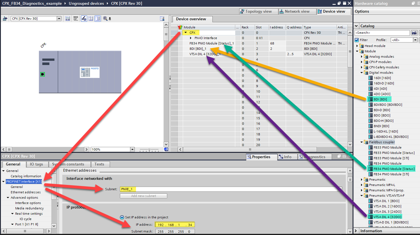
The following video clip shows you exactly how to view and modify these addresses for both the built-in I/O on the CPU and the expansion modules you added.
Device and Hardware configuration in TIA Portal (TIA Portal)
Let's see how to manage the I/O addresses for your entire PLC rack in the Device View.
Watch from 06:17 to 09:00. The presenter clicks on the device and uses the table in the main window to change the starting byte address for the inputs and outputs. Notice how changing the start address of a module shifts the addresses for all its channels automatically.
A Pro Tip for Simulation
When you use simulation software like Factory I/O (which we'll explore later for projects), it needs to write simulated sensor values to the PLC's input memory. If these memory locations overlap with physical inputs, the PLC hardware can overwrite the simulated values, causing issues. A common best practice is to offset the physical input addresses to a higher number, leaving the lower addresses free for simulation.
This guide from Factory I/O explains this exact step.
Setting up S7-1200/1500 - FACTORY I/O
This article explains a crucial best practice: offsetting physical I/O addresses to prepare for simulation.
Read step 10 in the 'Setting up communication between PC and PLC' section. It shows how to change the 'Start address' for the input addresses to 10, preventing conflicts with simulators that write to addresses starting from 0.
Configuring Module-Specific Properties
Some modules, especially analog ones, require more detailed configuration. For an analog input module, you must tell each channel what kind of signal to expect. Your sensor might output a 0-10V signal, or it might use a 4-20mA current loop. The module needs to know this to correctly interpret the data.
Device and Hardware configuration in TIA Portal (TIA Portal)
Finally, let's look at configuring the specific properties of an analog module's channels.
Watch from 09:00 to 11:51. The presenter selects an analog input module and, in the Inspector Window, navigates to the channel properties. Here, they set the 'Measurement type' (Voltage/Current) and the specific range for each channel to match different types of hypothetical sensors.
Another critical setting, especially when connecting to external software, is the PLC's protection level. By default, for security, a PLC might block communication requests. You often need to explicitly permit it.
Setting up S7-1200/1500 - FACTORY I/O
This is another key configuration step required for communication. It's like a firewall setting for the PLC.
Read step 11 in the same article. It shows how to find the 'Protection' settings and enable 'Permit access with PUT/GET communication from remote partner'. This is a common step you'll perform when setting up a new project.
Conclusion
Excellent work. You have now configured a complete virtual PLC system. You've gone from a single CPU to a fully specified rack with multiple I/O modules, a network address, and correctly assigned memory addresses for all inputs and outputs.
Key Takeaways:
- Hardware Configuration is done in the Device View by dragging modules from the Hardware Catalog onto the PLC rack.
- The CPU's IP address is a fundamental property set in the PROFINET interface settings, enabling network communication.
- Each I/O point is assigned a unique memory address (e.g.,
%I 10.0,%Q 4.1) that your program uses to interact with the physical world. - You can and should organize your I/O addresses logically by changing the start address of each module in the device's properties.
- Advanced modules, like analog inputs, require channel-specific configuration (e.g., setting voltage/current ranges) to match the connected sensors.
- Security settings, such as permitting PUT/GET communication, are often required to allow external devices to exchange data with the PLC.
Preview of the Next Lesson:
Your digital blueprint is complete. The next logical step is to bring this configuration to life. In the next lesson, you will learn how to compile your project, download it to a PLC (or a simulator), and establish an online connection. This will bridge the gap between your offline engineering work and a live, running controller.