Hello! Welcome back to the tenth module of the bootcamp.
In our previous lesson, we conducted a detailed comparison of I2C and SPI, focusing on the trade-offs between pin count, speed, and protocol complexity. You now have a solid framework for choosing between these two common on-board protocols.
Now, we shift our attention to a protocol that is a cornerstone of the automotive industry: the Controller Area Network (CAN). Given your extensive experience in automotive embedded systems, you are undoubtedly familiar with CAN's role. However, for interviews at top semiconductor firms, a precise, bit-level understanding of its mechanics—especially its unique arbitration and fault-tolerance features—is crucial. This lesson will focus on providing that deep, interview-ready knowledge.
Your learning outcome for this lesson is to: Explain the CAN and CAN-FD protocols, including frame format, bitwise arbitration, error frames, and bus-off recovery.
1. Classical CAN: Frame Format and Arbitration
CAN is a multi-master, message-based protocol designed for robust, real-time control. Unlike SPI or I2C, it doesn't use slave addresses. Instead, messages are broadcast with an identifier that determines their priority.
Let's begin by deconstructing the standard CAN data frame and understanding its most critical feature: non-destructive bitwise arbitration.
This video from Texas Instruments provides an excellent and clear walkthrough of the classical CAN frame structure and the arbitration process.
Watch the segments on frame structure (00:15 - 01:59) and arbitration (01:59 - 05:34). Pay close attention to: Frame Fields: The purpose of the Start of Frame (SOF), Identifier (Arbitration Field), Control Field (especially the DLC), Data Field, CRC, and ACK slot. Arbitration Logic: How the bus acts as a 'wired-AND' where a dominant '0' bit always wins against a recessive '1' bit. Priority: The principle that a lower identifier value means higher priority.
Dissecting the CAN Frame
As the video explained, a standard CAN 2.0A frame is a highly structured message.
The key fields you must know are:
- Start of Frame (SOF): A single dominant bit that synchronizes all nodes.
- Arbitration Field: Contains the 11-bit (for standard CAN) or 29-bit (for extended CAN) Identifier. This is where arbitration occurs.
- Control Field: Includes the Data Length Code (DLC), which specifies the number of data bytes (0-8).
- Data Field: Contains 0 to 8 bytes of payload data.
- CRC Field: A 15-bit Cyclic Redundancy Check for error detection.
- ACK Slot: A slot where the transmitter sends a recessive bit, and any receiving node can acknowledge successful, error-free reception by pulling the line dominant.
- End of Frame (EOF): A sequence of 7 recessive bits marking the end of the frame.
Non-Destructive Bitwise Arbitration
This is the genius of CAN. The physical layer is designed so that a dominant level (logic '0') physically overrides a recessive level (logic '1'). When multiple nodes start transmitting simultaneously, they also monitor the bus.

An interviewer might ask, "What happens when two CAN nodes transmit at the same time?" You should respond by explaining this non-destructive, bitwise arbitration process, emphasizing that the message with the lower numerical ID always wins the bus and its transmission is never corrupted, while the losing node automatically re-schedules its transmission for when the bus is next idle.
2. Error Handling and Fault Confinement
CAN's robustness comes from its sophisticated error detection and fault confinement mechanisms.
Error Detection and Error Frames
CAN nodes perform five types of error checks:
- Bit Monitoring: A transmitter checks if the bit level it's sending matches the level on the bus (this is also key to arbitration).
- Bit Stuffing: After five consecutive identical bits, a stuff bit of the opposite polarity is inserted to ensure enough edges for synchronization. A violation of this rule is a Stuff Error. The video from Texas Instruments covers this from 10:39 to 13:05.
- CRC Check: Receivers calculate the CRC on the message and compare it to the received CRC. A mismatch is a CRC Error.
- Frame Check: Checks for format violations in fields that have a fixed value (e.g., ACK delimiter, EOF). A violation is a Form Error.
- ACK Check: If a transmitter does not see a dominant level in the ACK slot, it's an ACK Error.
When any node detects any of these errors, it immediately transmits an Error Frame. An Error Frame consists of 6 dominant bits, which is a deliberate violation of the bit stuffing rule. This ensures all other nodes on the bus also detect an error and discard the corrupted message. The original transmitter will then automatically try to re-send the message.
Fault Confinement: Error States
To prevent a single faulty node from continuously disrupting the bus with error frames, each CAN controller maintains a Transmit Error Counter (TEC) and a Receive Error Counter (REC). Based on the values of these counters, a node operates in one of three states.
CAN protocol basics, PART 28, CAN Controller states, Error active, Error Passive and Bus-off.
This video from 'Secrets of Automotive Industry' clearly explains the three fault confinement states, which are a critical topic for any CAN-related interview.
Watch from 01:56 to 05:18. Focus on the conditions for entering each state and the behavior of the node in that state: Error Active: The normal operational state. Error Passive: The state for a moderately faulty node. Bus-Off: The state for a severely faulty node, effectively disconnecting it from the bus.
Here is a summary of the states:
| State | Condition | Behavior |
|---|---|---|
| Error Active | TEC <= 127 AND REC <= 127 |
Normal operation. Transmits Active Error Flags (6 dominant bits) upon detecting an error. |
| Error Passive | TEC > 127 OR REC > 127 |
Still participates in communication. Transmits Passive Error Flags (6 recessive bits), which don't disrupt other nodes. Must wait longer after transmitting before initiating a new transmission. |
| Bus-Off | TEC > 255 |
Node is switched off. It cannot transmit or receive any messages. This isolates the faulty node to protect the network. Recovery typically requires application-level intervention or a reset. |
An interviewer may ask, "What is bus-off recovery?" Your answer should explain that a node enters the bus-off state when its Transmit Error Counter exceeds 255. It is then disconnected from the bus to prevent network disruption. Recovery is not automatic at the protocol level; it requires the host microcontroller to re-initialize the CAN controller, often after a specific delay, once the underlying fault is presumed to be resolved.
3. CAN FD: The Next Generation
As vehicle systems grew more complex, the 8-byte payload and 1 Mbit/s speed of classical CAN became a bottleneck. CAN with Flexible Data-Rate (CAN FD) was developed to address this.
Inside CAN FD: Architecture, Performance Gains, and Integration ...
This article from Copperhill Technologies provides a fantastic deep dive into CAN FD, covering its motivation, features, and differences from classical CAN. It's an excellent resource for a detailed, technical understanding.
Read the sections on 'Increased Payload Capacity', 'Flexible Data-Rate', 'Frame Structure Changes', 'Enhanced CRC', the 'Comparison with Classical CAN' table, and the 'Backward Compatibility' paragraph. This will give you a complete picture of what makes CAN FD different.
Key Enhancements of CAN FD
Let's summarize the key improvements from the article.
- Increased Payload: The maximum data field size is increased from 8 bytes to 64 bytes. This dramatically improves efficiency by reducing the protocol overhead per byte.
- Flexible Data-Rate: This is the core feature. The CAN frame is split into two phases:
- Arbitration Phase: Runs at the standard CAN bit rate (e.g., 500 kbit/s), ensuring backward compatibility with arbitration logic.
- Data Phase: After arbitration, the bus can switch to a much higher bit rate (e.g., 2 or 5 Mbit/s) for the data and CRC fields.
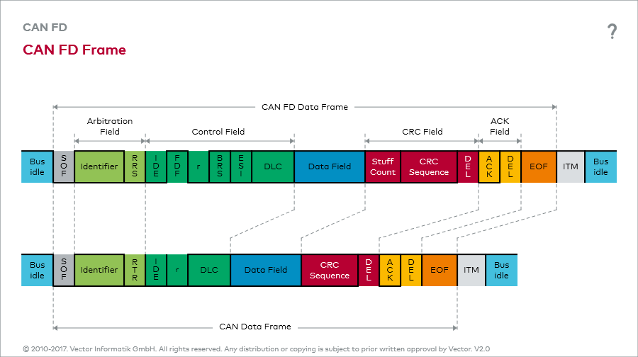
- Frame Format Changes:
- FDF (FD Format) bit: A new bit in the control field is set to '1' (recessive) to mark the frame as a CAN FD frame.
- BRS (Bit Rate Switch) bit: If set, indicates the switch to the higher bit rate for the data phase.
- ESI (Error State Indicator) bit: A bit that explicitly broadcasts whether the transmitting node is in the Error-Passive state.
- Enhanced CRC: The CRC polynomial is longer (17-bit or 21-bit, depending on payload size) to maintain high error-detection reliability for the larger frames.
- No Remote Frames: The concept of Remote Transmission Request (RTR) frames was removed to simplify the protocol.
A crucial point to remember is compatibility. A classical CAN controller cannot understand a CAN FD frame. If a CAN FD frame is sent on a bus with legacy nodes, those nodes will flag a form error, disrupting the network. Therefore, all nodes on a segment must be CAN FD-capable to use FD frames.
Conclusion
You have now reinforced your understanding of CAN and taken a deep dive into the specific mechanisms that are prime targets for interview questions. You can confidently explain not just what CAN does, but precisely how it achieves its renowned reliability and real-time performance.
Key Takeaways:
- Classical CAN relies on non-destructive bitwise arbitration based on message identifiers, where lower IDs have higher priority.
- Its robustness comes from multiple error detection mechanisms (CRC, stuffing, etc.) and a fault confinement system that transitions nodes between Error Active, Error Passive, and Bus-Off states.
- CAN FD enhances classical CAN by increasing the payload to 64 bytes and introducing a flexible data rate, where the data phase can run much faster than the arbitration phase.
- CAN FD introduces new frame control bits (FDF, BRS, ESI) but is not forward-compatible; legacy CAN nodes will generate errors if they see an FD frame.
Preview of the Next Lesson:
We have now covered the most important synchronous serial protocols (SPI) and robust multi-point buses (I2C, CAN). In our next lesson, we will examine the most common asynchronous protocol: UART. We will cover its operation, including baud rate calculation, parity, and hardware flow control (CTS/RTS).