Hello! Welcome to the next lesson in our embedded interview bootcamp.
In the previous lesson, we completed our tour of common serial buses by examining the CAN protocol, focusing on its arbitration, error handling, and the high-speed CAN FD variant. You are now well-equipped to discuss the trade-offs between I2C, SPI, and CAN.
Today, we shift our focus from synchronous and multi-master buses to the most ubiquitous asynchronous point-to-point protocol: the Universal Asynchronous Receiver-Transmitter (UART). While you have certainly used UART throughout your career, interviewers at semiconductor companies will expect you to explain exactly how it works under the hood, particularly regarding timing and flow control.
Your learning outcome for this lesson is to: Describe the operation of a UART, including baud rate calculation, parity, and hardware flow control (CTS/RTS).
1. UART Fundamentals: Asynchronous Operation and Data Framing
Unlike synchronous protocols like I2C or SPI, UART does not use a shared clock line. The "asynchronous" nature means that both the transmitter and receiver must agree on the communication speed beforehand and use their own internal clocks for timing. This timing is re-synchronized at the beginning of every byte.
Communication is built upon a simple data frame structure. Let's review these fundamentals.
UART Protocol: Understanding Serial Communication for Engineers
This article from Wevolver provides a solid overview of UART principles. We will focus on the sections that define the data frame and its components.
Please read the sections titled 'Fundamentals of UART Communication' and 'UART Data Framing and Timing'. Focus on understanding the role and logic level of each part of the data frame: Start Bit (synchronization) Data Bits (the payload, LSB first) Parity Bit (optional error checking) Stop Bit(s) (framing and idle state)
As the article describes, a UART frame encapsulates each byte of data with synchronization and error-checking bits. The line is held at a high logic level when idle. A transmission begins with a Start Bit, which is always a low logic level. This high-to-low transition signals to the receiver that a new frame is arriving and provides a timing reference.
The start bit is followed by the data bits (typically 5 to 9, with 8 being the most common), sent least-significant-bit (LSB) first. An optional Parity Bit may follow for basic error detection. The frame concludes with one or two Stop Bits, which are always a high logic level. This ensures the line returns to its idle state, ready for the next frame's start bit.
The most common configuration you'll encounter is 8N1: 8 data bits, No parity, and 1 stop bit.
2. Baud Rate Calculation and Timing Tolerance
Since there is no shared clock, how do the two devices stay synchronized? They both generate an internal clock at a pre-agreed frequency, the baud rate, which defines the time duration of a single bit. This is typically derived from a higher-frequency system clock.
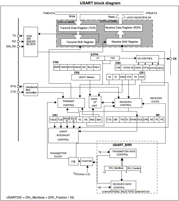
The core of baud rate generation is a clock divider. The fundamental equation is:
Where:
- Source Clock Frequency is the frequency of the clock feeding the UART peripheral (e.g., 8 MHz, 48 MHz).
- DIV is the integer divisor value you program into the UART's baud rate register.
- 16 is the typical oversampling rate. The receiver samples the line 16 times per bit period to reliably find the center of each bit, making the communication robust against minor clock drift.
Because the divisor DIV must be an integer, it's often impossible to achieve the desired baud rate with zero error.
This brief application note from NXP provides the exact formulas and a clear, practical example of calculating the divisor value and the resulting baud rate error.
Read Section 2, 'Baud rate calculation'. It's very short. Pay close attention to Example 2, where rounding the divisor results in a baud rate error. The calculation of this percentage error is a classic interview exercise.
A small error (typically < 2-3%) is acceptable because the timing is reset by the start bit of each frame. However, the error accumulates across the frame. A larger error can cause the receiver to sample the last few bits at the wrong time, leading to corrupted data.
To truly understand the effect of this error, let's see it in action.
14.1(d) - Serial Communication on the MSP430: The UART - Configuring the Baud Rate
This video provides an excellent visualization of what happens when the baud rate error is too high and how bit sampling fails.
Watch the segment from 01:51 to 07:35. The presenter calculates a baud rate with an 8.5% error and then draws the timing diagrams to show how the receiver's sampling points drift and eventually land on the wrong bits. This is a powerful illustration of why accurate baud rate generation is critical.
Interview Tip: If asked about UART timing, you should be able to explain that both devices use independent clocks configured to the same baud rate. Explain the role of the start bit for synchronization and the concept of oversampling for noise immunity. Be prepared to walk through the calculation of a divisor for a given system clock and baud rate, and to calculate the resulting percentage error.
3. Hardware Flow Control (RTS/CTS)
What happens if a fast device sends UART data to a slower device that can't process it quickly enough? The receiver's input buffer will overflow, and data will be lost. Hardware flow control is the mechanism to prevent this.
It uses two additional signal lines:
- RTS (Request to Send): An output signal from a receiver to the sender. When asserted, it means "I am ready to receive data."
- CTS (Clear to Send): An input signal on a sender. It receives the RTS signal from the other device. The sender will only transmit data if its CTS pin is asserted.
Note the slightly confusing naming. A device asserts its RTS to signal its readiness; the other device sees this on its CTS line and knows it is "clear to send."
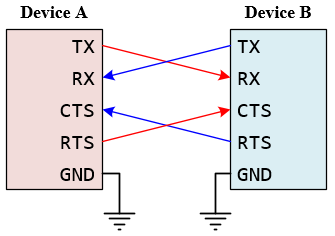
The logic is typically implemented using "high" and "low watermarks" in the receiver's software buffer.
- When the buffer fills up past a high watermark (e.g., 80% full), the receiver de-asserts its RTS line, telling the sender to pause.
- The sender sees its CTS line go low and stops transmitting.
- As the receiver processes data and the buffer level drops below a low watermark (e.g., 20% full), it re-asserts its RTS line.
- The sender sees its CTS line go high and resumes transmission.
Ben Eater's video on RS232 flow control is a masterclass in explaining this concept from first principles. He demonstrates the problem, the hardware solution, and the software logic.
Watch from the beginning to 08:33. Pay close attention to: (00:00 - 00:56) The problem: buffer overflow. (00:56 - 03:34) The introduction of the RTS/CTS signals and their purpose. (05:14 - 08:33) The BIOS code implementation showing how the RTS signal is controlled based on the buffer's fill level (high/low watermarks).
Hardware flow control is essential in scenarios involving high data rates or devices with differing processing speeds, such as a microcontroller communicating with a cellular or Wi-Fi modem.
Conclusion
In this lesson, you have taken a detailed look at the operational mechanics of UART, a fundamental protocol in embedded systems. While conceptually simple, a deep understanding of its timing, error handling, and flow control is a key differentiator in technical interviews.
Key Takeaways:
- UART is asynchronous: It relies on pre-configured timing (baud rate) and uses Start/Stop bits for frame synchronization.
- Baud Rate Generation: The baud rate is derived from a system clock via an integer divider. This often results in a small percentage error, which is tolerable up to a point due to oversampling and per-frame resynchronization.
- Data Frame: The standard
8N1format consists of 1 start bit, 8 data bits, and 1 stop bit, for a total of 10 bits to transmit one byte. - Parity: An optional bit can be added to detect single-bit errors in transmission.
- Hardware Flow Control (RTS/CTS): A crucial mechanism that uses two extra wires to allow a receiver to pause a sender, preventing buffer overruns.
Preview of the Next Lesson:
Having covered the main external communication protocols (I2C, SPI, CAN, UART), we will now move inside the System-on-Chip (SoC). Our next lesson will explore the backbone of the chip itself: the bus protocols that connect the CPU to its peripherals. We will explain the roles of different SoC bus protocols (AXI, AHB, APB) in connecting high-speed and low-speed peripherals. This is critical knowledge for anyone looking to work at a semiconductor design company.