Hello! Welcome to the tenth module of your Embedded Interview Preparation Bootcamp.
In our last module, we concluded our deep dive into Linux device drivers by mastering mmap, a powerful technique for high-performance I/O between user space and kernel space. We've now moved from the highest levels of the driver software stack down to the lowest. This module shifts our focus to the physical layer: the hardware protocols that allow the SoC to communicate with the outside world. Understanding these protocols at the bit level is non-negotiable for interviews at leading semiconductor companies.
Your learning outcome for this lesson is to: Compare I2C and SPI protocols, detailing signaling, addressing, clocking (CPOL/CPHA), and multi-master arbitration.
This is a classic and fundamental topic. Your ability to articulate the precise differences, trade-offs, and underlying mechanisms will be a strong signal of your expertise.
1. SPI: The Serial Peripheral Interface
We'll begin with SPI, as it's generally simpler from a protocol standpoint. SPI is a synchronous, serial communication interface that operates in a master-slave paradigm, typically with a single master and one or more slaves. It's known for its simplicity and high speed.
To get a comprehensive overview of SPI's operation, including its wiring and the critical clocking modes, let's watch the following video segment.
I2C, SPI, UART - In Depth Embedded Protocols!
This video from hoff._world provides an excellent visual and conceptual introduction to the SPI protocol.
Watch the segment from 01:31 to 09:25. Pay close attention to: The four primary signal lines: MOSI, MISO, SCLK, and CS. How the Chip Select (CS) line is used to address a specific slave device. The graphical explanation of the four SPI clocking modes, defined by Clock Polarity (CPOL) and Clock Phase (CPHA). This is a very common interview topic.
Key SPI Characteristics
Let's break down what you just watched into the core concepts you need to know for an interview.
Signaling and Pinout:
SPI is fundamentally a 4-wire interface for a single slave, and each additional slave requires one extra wire.
- SCLK (Serial Clock): The clock signal driven by the master that synchronizes the data transfer.
- MOSI (Master Out, Slave In): The data line for sending data from the master to the slave.
- MISO (Master In, Slave Out): The data line for sending data from the slave back to the master.
- CS/SS (Chip Select / Slave Select): A dedicated line from the master to each slave. The master pulls this line low to activate a specific slave.
Because MOSI and MISO are separate lines, SPI communication is full-duplex, meaning data can be sent and received simultaneously. This is a key advantage for applications requiring high-throughput, bidirectional data streaming (e.g., interacting with an ADC while configuring it).
Clocking Modes (CPOL/CPHA)
As the video explained, the combination of Clock Polarity (CPOL) and Clock Phase (CPHA) defines four distinct modes of operation. This determines the idle state of the clock and on which clock edge data is sampled.
- CPOL=0: Clock is idle LOW.
- CPOL=1: Clock is idle HIGH.
- CPHA=0: Data is sampled on the first clock edge (rising for CPOL=0, falling for CPOL=1).
- CPHA=1: Data is sampled on the second clock edge (falling for CPOL=0, rising for CPOL=1).
It's crucial that the master and the selected slave are configured for the same mode.

An interviewer might ask, "Can you draw the timing diagram for SPI Mode 3?" You should be able to sketch a clock that is idle HIGH (CPOL=1) and show data being sampled on the rising edge (the second edge, CPHA=1).
2. I2C: The Inter-Integrated Circuit Protocol
Now let's turn to I2C. While also a master-slave protocol, I2C is fundamentally different in its physical layer, addressing, and protocol complexity. Its primary advantage is the minimal pin count.
Let's get an initial overview of the I2C protocol flow.
I2C, SPI, UART - In Depth Embedded Protocols!
The same video provides a great introduction to I2C, contrasting it well with SPI.
Watch the segment from 11:26 to 18:01. Focus on: The two-wire (SDA, SCL) architecture. The concept of software addressing to select a slave. The basic transaction flow: START, Address, R/W bit, ACK/NACK, Data, and STOP.
Deeper Dive into I2C Mechanisms
I2C has several features that are more complex than SPI but enable its unique capabilities. To understand these in detail, we'll turn to a more formal document.
[PDF] AN10216-01 I2C Manual - NXP Semiconductors
The NXP I2C Manual is an authoritative source. Reading these sections will give you the precise terminology and deep understanding of I2C's advanced features that are expected in a senior-level interview.
Read through the 'I2C Overview' section and the 'I2C Bus Terminology' slide (pages 10-15). As you read, focus on these key concepts: Hardware Architecture: Understand the open-drain outputs and the need for pull-up resistors. START/STOP Conditions: How are these special conditions signaled differently from data bits? Addressing: How the 7-bit address and R/W bit work. Multi-Master and Arbitration: Grasp the concept of multiple masters on one bus and the process that determines who wins control. Clock Stretching: Note this feature, which allows a slave to pause the communication.
Let's summarize these crucial I2C characteristics.
Signaling and Physical Layer:
- SCL (Serial Clock): The clock line, controlled by the master.
- SDA (Serial Data): The bidirectional data line.
I2C is half-duplex. Data can travel in only one direction at a time on the single SDA line. The key physical-layer feature is that both lines are open-drain. This means a device can only pull the line LOW. To make the line go HIGH, all devices must release it, allowing external pull-up resistors to pull the voltage up. This wired-AND logic is what makes multi-master arbitration possible.
Protocol Flow and Reliability:
An I2C transaction is highly structured:
- START (S): Master pulls SDA low while SCL is high.
- Address Frame: Master sends the 7-bit slave address followed by a Read/Write bit (0=Write, 1=Read).
- Acknowledge (ACK): The addressed slave pulls SDA low for one clock cycle to acknowledge it is present. If the master doesn't receive an ACK (the line remains high), it's a Not Acknowledge (NACK).
- Data Frames: Data is sent in 8-bit bytes, with each byte followed by an ACK/NACK bit.
- STOP (P): Master pulls SDA high while SCL is high.
The built-in ACK/NACK mechanism provides protocol-level reliability that SPI lacks.
Multi-Master Arbitration:
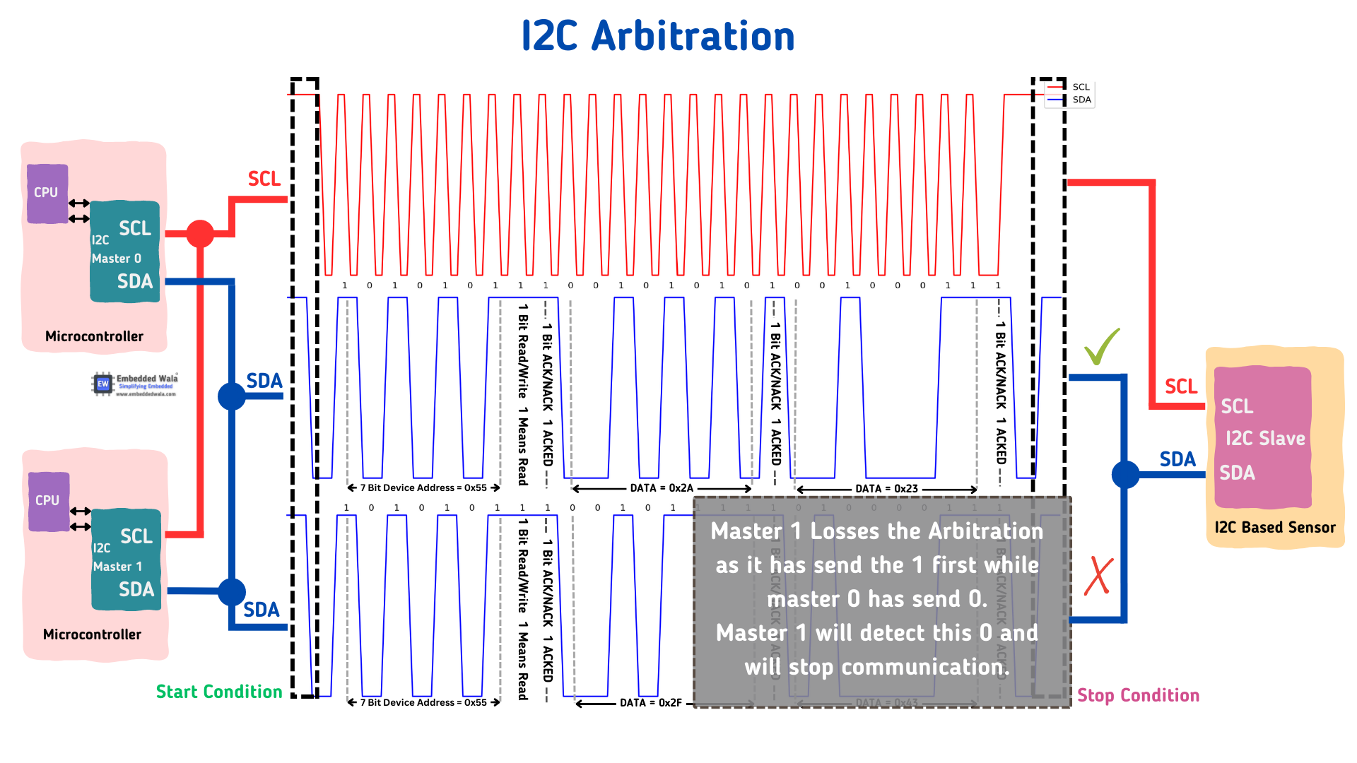
This is I2C's most sophisticated feature. If two masters start a transmission at the same time, they both begin sending their data. Because the bus is open-drain, if one master sends a '0' (pulls the line low) and another attempts to send a '1' (releases the line), the line will be LOW. The master that attempted to send the '1' will detect that the line did not go high as expected. It immediately knows it has lost arbitration and stops its transmission, leaving the winning master to continue without data corruption.
3. Comparison and Interview-Ready Trade-offs
Choosing between I2C and SPI is a classic system design question. The answer depends entirely on the requirements. The following video provides a concise summary of the trade-offs.
I2C vs SPI - Which one to select for your design
This video from Bina Bhatt directly compares the two protocols from a design selection perspective.
Watch the entire video (around 5 minutes). It effectively summarizes the key differences in pin count, duplexing, speed, reliability, and multi-master support.
Here is a summary table that captures the essential points for an interview:
| Feature | SPI (Serial Peripheral Interface) | I2C (Inter-Integrated Circuit) |
|---|---|---|
| Pin Count | 4 + N (where N is the number of slaves) | 2 (SDA, SCL) for the entire bus |
| Data Rate | High (often >10 MHz, no theoretical limit) | Lower (Std: 100kbps, Fast: 400kbps, up to 5Mbps in UFm) |
| Duplex | Full-Duplex (simultaneous send/receive) | Half-Duplex (send or receive, not both) |
| Slave Selection | Hardware-based via dedicated Chip Select (CS) lines. | Software-based via a unique 7-bit or 10-bit address on the bus. |
| Reliability | No built-in acknowledgment. Master doesn't know if slave exists. | Built-in ACK/NACK bit after each byte transfer. |
| Multi-Master | Not supported by the protocol. Typically single-master. | Supported via a well-defined arbitration mechanism. |
| Hardware Complexity | More pins. Push-pull drivers. Simple shift-register logic. | Fewer pins. Open-drain drivers with pull-up resistors are required. |
| Protocol Complexity | Very simple. Master controls everything, just clocks bits out/in. | More complex. Requires handling START/STOP, addresses, ACKs, arbitration. |
| Typical Use Case | High-speed data streaming: ADCs, DACs, Flash memory, displays. | Control and configuration of many low/medium-speed devices: sensors, RTCs, EEPROMs. |
Interview Perspective:
-
Question: "You need to connect 10 temperature sensors to a microcontroller with limited GPIOs. Which protocol would you choose and why?"
- Your Answer: "I would choose I2C. With only two wires, SCL and SDA, I can connect all 10 sensors to the same bus, assuming they have unique I2C addresses. This is far more pin-efficient than SPI, which would require 10 dedicated chip select lines in addition to its other three bus lines."
-
Question: "Explain how arbitration works on an I2C bus."
- Your Answer: "I2C arbitration is possible because of its open-drain physical layer. If two masters start transmitting simultaneously, they monitor the SDA line while sending. The first time one master tries to send a '1' (releasing the line) while another sends a '0' (pulling the line low), the master sending the '1' will read back a '0' from the bus. It immediately recognizes it has lost arbitration, stops driving the bus, and waits for a STOP condition. The winning master's message remains uncorrupted and continues seamlessly."
-
Question: "You're interfacing with a high-resolution camera sensor that streams data continuously. Which protocol is more suitable and why?"
- Your Answer: "SPI is the clear choice. Its full-duplex nature and much higher potential clock speed are ideal for high-throughput, continuous data streaming. I2C's lower speed and half-duplex communication would likely create a bottleneck."
Conclusion
You now have a detailed, comparative understanding of I2C and SPI, covering their signaling, clocking, addressing, and unique features like arbitration. This knowledge is fundamental for any embedded systems role, especially in the semiconductor industry where you might be involved in designing or validating the peripheral hardware itself.
Key Takeaways:
- SPI is a simple, high-speed, full-duplex protocol ideal for data streaming to a limited number of slaves, using dedicated chip select lines.
- I2C is a more complex, slower, half-duplex protocol optimized for controlling many devices on a two-wire bus, featuring software addressing, built-in acknowledgments, and multi-master support through arbitration.
- The choice between them is a classic engineering trade-off between speed, pin count, and the number of connected devices.
Preview of the Next Lesson:
Having compared two common on-board protocols, we will next turn our attention to a robust bus protocol that is ubiquitous in the automotive world and industrial control systems. Given your background, this should be a familiar topic, but we will dive into the details crucial for a deep system-level understanding. Our next lesson is to explain the CAN and CAN-FD protocols, including frame format, bitwise arbitration, error frames, and bus-off recovery.