Hello! Welcome back to our Embedded Interview Preparation Bootcamp.
In our last lesson, we demystified the startup process, tracing the execution path from processor reset to main(). We saw how the startup code relies on special symbols provided by the linker (like _sdata, _edata, _sbss, _ebss) to initialize the .data and .bss sections correctly.
This naturally leads to a crucial question: how does the linker decide where these sections go and how are those symbols created? The answer lies in the linker script, the blueprint for your program's memory map. Mastering linker scripts is a hallmark of a senior embedded engineer, as it grants you ultimate control over how your application is laid out in memory.
Today, your goal is to: Write and modify linker scripts to control memory regions and section placement for embedded targets. We will explore the syntax and concepts needed to build a linker script from the ground up, ensuring your code and data land exactly where they need to be on the microcontroller.
The Linker's Blueprint
Before diving into the syntax, let's form a mental model. The linker's job is to take all your compiled object files (.o files) and merge them into a single executable file (.elf file). The linker script instructs the linker on how to perform this merge, specifically by mapping the input sections from your object files (e.g., .text, .data) to the physical memory regions of your target hardware (e.g., FLASH, SRAM).
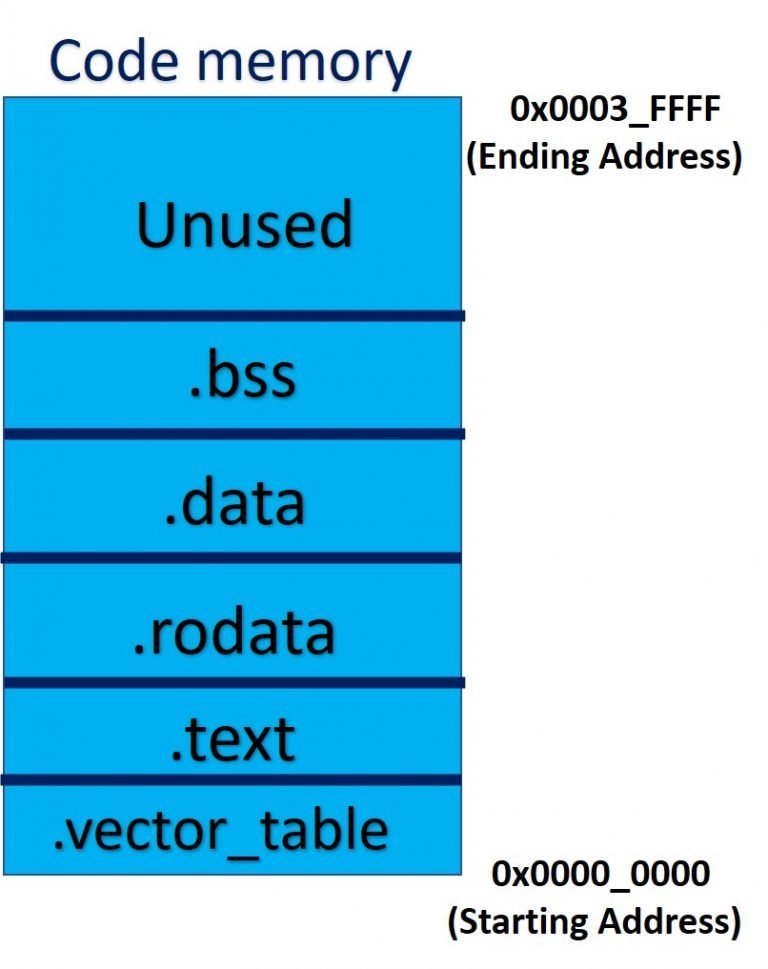
A linker script primarily consists of two main commands:
MEMORY: Describes the physical memory map of your microcontroller (e.g., "There is FLASH at address X with size Y").SECTIONS: Defines the output sections of your program (e.g.,.text,.data) and specifies which input sections from your object files go into them, and which memory region they should be placed in.
To get a quick, high-level overview of these components, please start by reading the following sections from the "Interrupt" blog.
From Zero to main(): Demystifying Firmware Linker Scripts
The article 'From Zero to main(): Demystifying Firmware Linker Scripts' provides an excellent introduction to the core components of a linker script.
Please read the sections 'Anatomy of a Linker Script' and 'Memory Layout'. This will introduce the four main parts of a script and detail the MEMORY command.
The MEMORY Command: Describing the Hardware
As you just read, the MEMORY command tells the linker about the target's physical memory. For any given microcontroller, you can find this information in its datasheet.
For example, a device might have:
- 256KB of FLASH memory starting at
0x08000000 - 64KB of SRAM starting at
0x20000000
In a linker script, this is defined as:
MEMORY
{
  FLASH (rx) : ORIGIN = 0x08000000, LENGTH = 256K
  RAM   (rwx): ORIGIN = 0x20000000, LENGTH = 64K
}
FLASHandRAMare arbitrary names for the regions.(rx)and(rwx)are attributes describing the memory permissions (read, write, execute). The linker can use these to warn you if you try to place, for example, writable data into a read-only region.ORIGINis the start address.LENGTHis the size. You can use suffixes likeKfor kilobytes andMfor megabytes.
The following video segment provides a detailed walkthrough of this MEMORY command and the overall structure of a linker script.
ARM - M: Build process, role of linker and Linker scripts! | Embedded Systems podcast, in Pyjama!
The video 'ARM - M: Build process, role of linker and Linker scripts!' offers a practical guide to linker script syntax.
Watch from 00:33:19 to 00:38:33. This segment explains the MEMORY command syntax in detail, covering region names, attributes, ORIGIN, and LENGTH.
The SECTIONS Command: Placing Code and Data
This is where the real work happens. The SECTIONS block tells the linker how to assemble the final executable. Let's build it up, section by section.
The Location Counter and .text Section
The linker uses a special variable, the location counter (.), to keep track of the current address while it's filling up memory.
A typical .text section definition looks like this:
SECTIONS
{
  .text :
  {
    KEEP(*(.isr_vector))  /* Place the vector table first and don't discard it */
    *(.text*)            /* Place all input .text and .text.* sections */
    *(.rodata*)          /* Place all read-only data */
  } > FLASH              /* Place this entire output section in the FLASH region */
}
>FLASH: This directs the entire output section into theFLASHmemory region we defined earlier.KEEP(*(.isr_vector)): Ensures the interrupt vector table is placed first and is never optimized away by the linker, which is critical for the CPU to boot correctly.*(.text*): This is a wildcard pattern. It tells the linker to take the.textsections from all input object files (*) and place them here.
This next video segment walks through the SECTIONS syntax, explaining the location counter (.), how to define symbols, and the KEEP keyword.
ARM - M: Build process, role of linker and Linker scripts! | Embedded Systems podcast, in Pyjama!
Let's continue with the same video to understand the SECTIONS command.
Watch from 00:38:33 to 00:46:14. Pay close attention to the explanation of the output section, input section patterns (wildcards), the location counter (.), and the purpose of KEEP.
The Hard Part: LMA vs. VMA and the .data Section
This is the most critical concept for creating a functional bare-metal system.
- Virtual Memory Address (VMA): The address where code expects a variable to be during runtime. For
.datavariables, this must be in RAM. - Load Memory Address (LMA): The address where the section is initially loaded by the programmer/debugger. For the initial values of
.datavariables, this must be in non-volatile FLASH.
As we saw in the last lesson, the startup code's job is to copy these initial values from the LMA (in FLASH) to the VMA (in RAM). The linker script is what makes this possible using the AT keyword.
.data :
{
  /* .data sections from all input files */
  *(.data*)
} > RAM AT > FLASH
This syntax instructs the linker:
- The runtime location (VMA) for the
.datasection is in theRAMregion. - But, load the initial values for this section at a location (LMA) in the
FLASHregion.
The linker then calculates the LMA and VMA, which we can export as symbols for our startup code.
This is a complex topic, so we'll review it from two perspectives. First, a deep theoretical dive, and second, a practical demonstration of what happens when you get it wrong.
ARM - M: Build process, role of linker and Linker scripts! | Embedded Systems podcast, in Pyjama!
This segment from the 'inpyjama' podcast provides a fantastic, in-depth explanation of the LMA vs. VMA problem and the AT > FLASH solution.
Watch from 01:00:54 to 01:16:11. The hosts discuss exactly why global variables (.data) must be placed in RAM (for writability) but their initial values must be stored in FLASH (for persistence). They then connect this directly to the > RAM AT > FLASH syntax.
Now, let's see the practical consequences. What happens if you tell the linker to put .data in FLASH? You get a hard fault when you try to write to a global variable. The next video demonstrates this failure and the fix.
The 'How a Microcontroller starts' video by Artful Bytes gives a great practical demonstration of a hard fault caused by an incorrect linker script and shows the fix.
Please watch from 00:19:06 to 00:21:42. First, you'll see a program crash with a hard fault. The narrator uses the debugger to find that the code is trying to write to a variable located in FLASH. Then, you'll see the linker script being modified to correctly place the .data and .bss sections in RAM, using the AT keyword for .data.
Defining Symbols for Startup Code
We can now complete the circle. The linker script defines the symbols that our startup code uses to perform the memory initialization. We do this by assigning the value of the location counter . to a symbol name.
The article "Mastering the GNU linker script" provides a perfect example of this.
Mastering the GNU linker script
This article from AllThingsEmbedded provides a clear, text-based reference for defining symbols and using the LOADADDR function.
Read the section 'Specifying symbols in the linker script'. It shows exactly how to define the start, end, and size of the .data section and, crucially, how to get its LMA using LOADADDR(.data). This provides all the pieces the startup code needs.
Putting it all together, a complete linker script might look like this:
/* Define Memory Regions */
MEMORY
{
  FLASH (rx) : ORIGIN = 0x08000000, LENGTH = 256K
  RAM   (rwx): ORIGIN = 0x20000000, LENGTH = 64K
}

/* Define entry point */
ENTRY(Reset_Handler)

/* Define a symbol for stack size */
_stack_size = 2K;

SECTIONS
{
  .text :
  {
    KEEP(*(.isr_vector))
    *(.text*)
    *(.rodata*)
    _etext = .; /* Symbol for end of .text */
  } > FLASH

  /* LMA of .data is right after .text in FLASH */
  _sidata = LOADADDR(.data);

  .data :
  {
    _sdata = .; /* VMA start of .data in RAM */
    *(.data*)
    _edata = .; /* VMA end of .data in RAM */
  } > RAM AT > FLASH

  .bss :
  {
    _sbss = .; /* Start of .bss in RAM */
    *(.bss*)
    *(COMMON)
    _ebss = .; /* End of .bss in RAM */
  } > RAM

  .stack (NOLOAD) :
  {
      . = . + _stack_size;
      _estack = .; /* Define a symbol for the top of the stack */
  } > RAM
}
Advanced Control: Placing Custom Sections
Finally, you can combine linker scripts with compiler attributes to place specific functions or data at precise locations. This is an advanced technique used for performance optimization (e.g., placing critical code in fast memory) or mapping structures to hardware registers.
You declare a variable or function in a custom section in your C code:
// Place my_critical_buffer in a special section named ".fast_ram"
uint8_t my_critical_buffer[1024] __attribute__((section(".fast_ram")));
Then, you add an entry for that section in your linker script, placing it wherever you need. This technique is often used to map a C struct directly onto a memory-mapped peripheral register block, providing a structured way to access hardware.
Conclusion
You have now explored the core mechanics of the GNU linker script, a powerful tool that gives you complete control over your application's memory map. Being able to read, modify, and write these scripts from scratch is a key differentiator for senior embedded roles, especially in semiconductor companies where you might be bringing up new silicon.
Key Takeaways:
- The
MEMORYcommand describes the physical memory regions of your target device. - The
SECTIONScommand maps input sections from object files into output sections in the final executable. - Understanding the difference between LMA (Load Memory Address) and VMA (Virtual Memory Address) is critical for bare-metal systems.
- The
> RAM AT > FLASHsyntax is the key to correctly handling initialized data (.datasection) that lives in RAM but is stored in FLASH. - You can define symbols in the linker script using the location counter (
.) to provide start/end addresses to your C startup code.
Preview of the Next Lesson:
In this lesson, we focused on the final stage of the build process. Next, we will zoom out to look at the entire toolchain. We will discuss how to set up a cross-compilation toolchain and use target-specific optimization flags, which are essential skills when developing software for a processor architecture different from your development machine.